
Autostereoscopic three-dimensional image display device using time division

a three-dimensional image and display device technology, applied in the field of autostereoscopic three-dimensional (3d) image display devices, can solve the problems of reducing the quality of an image, affecting the commercialization of autostereoscopic 3d image display devices, and uneven horizontal brightness of each of the so as to minimize the reduction in the resolution of a 3d image, reduce the crosstalk of binocular viewing point images, and minimize the effect of the brightness chang

Active Publication Date: 2019-05-07
SAMSUNG ELECTRONICS CO LTD
View PDF23 Cites 3 Cited by
  • Summary
  • Abstract
  • Description
  • Claims
  • Application Information

AI Technical Summary

Benefits of technology

[0010]The present invention is directed to provide an autostereoscopic 3D image display device using a line source and a pupil tracking system. The present invention minimizes brightness change of a 3D image caused by movement of a viewer in a conventional autostereoscopic 3D image display device, reduces crosstalk of binocular viewing point images of a viewer to that of a glasses-type 3D image display device, and minimizes reduction in the resolution of a 3D image.
[0011]The present invention is also directed to provide an autostereoscopic 3D image display device that overcomes the limitation of a position from which a viewer can view the optimum 3D image. Particularly, the present invention enables a viewer to view a 3D image of equal quality to an image viewed from the optimum viewing position, even when the viewer is moving in the distance direction (depth direction) to the 3D image display device.
[0012]The present invention is also directed to provide an autostereoscopic 3D image display device that overcomes the limitation of a conventional autostereoscopic 3D image display device that it can provide an optimum 3D image to only one viewer or can provide a 3D image to a plurality of viewers only within a range where movement is very restricted, and thus enables a plurality of viewers to continuously view natural 3D images while dynamically moving.

Problems solved by technology

However, there are some limitations in commercializing autostereoscopic 3D image display devices at present.
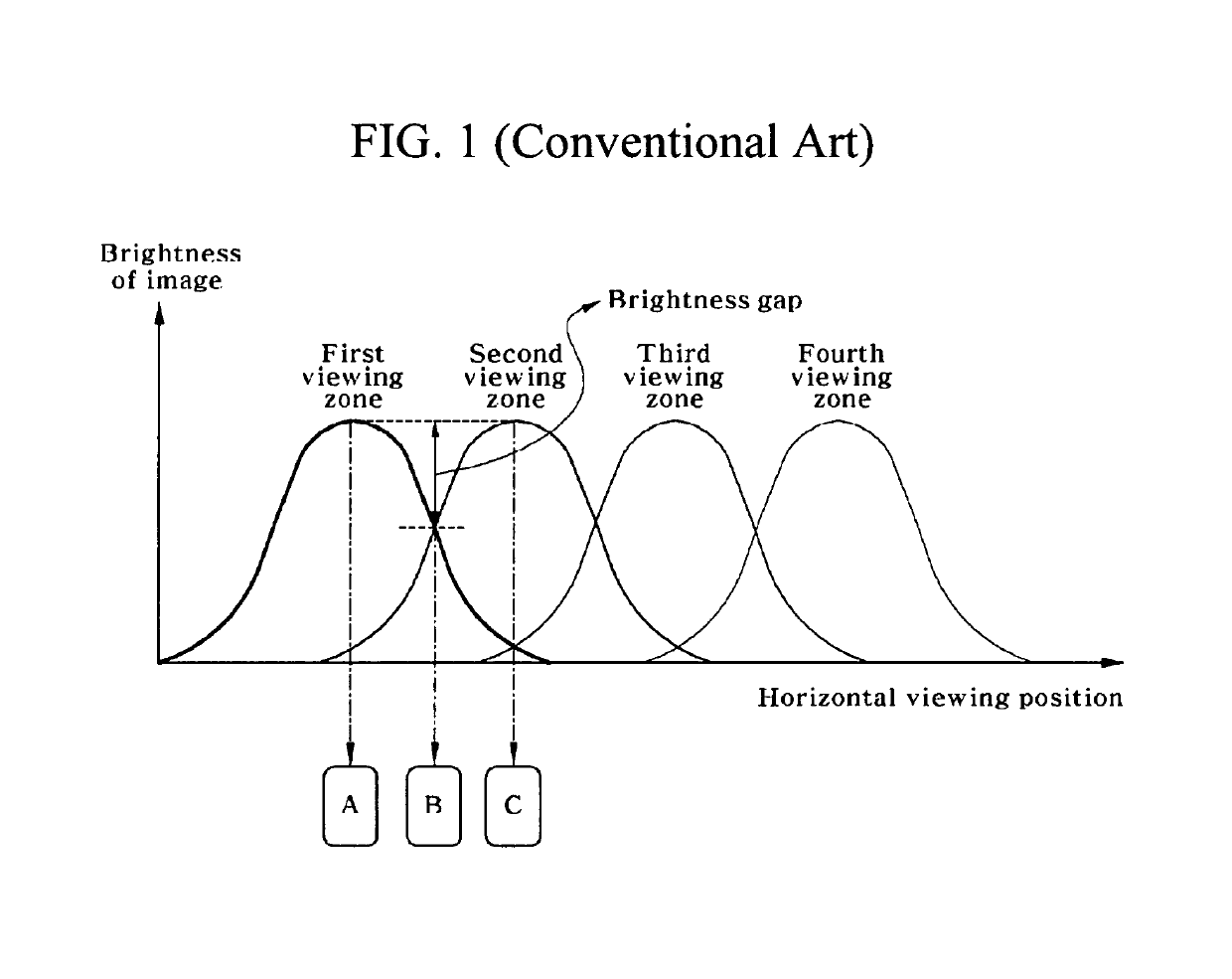
First, crosstalk occurs between binocular viewing point images, and the brightness of each of the binocular viewing point images is not uniform horizontally.
Due to this reason, a viewer feels severe fatigue when continuously viewing 3D images, and the quality of an image is degraded even by slight horizontal movement.
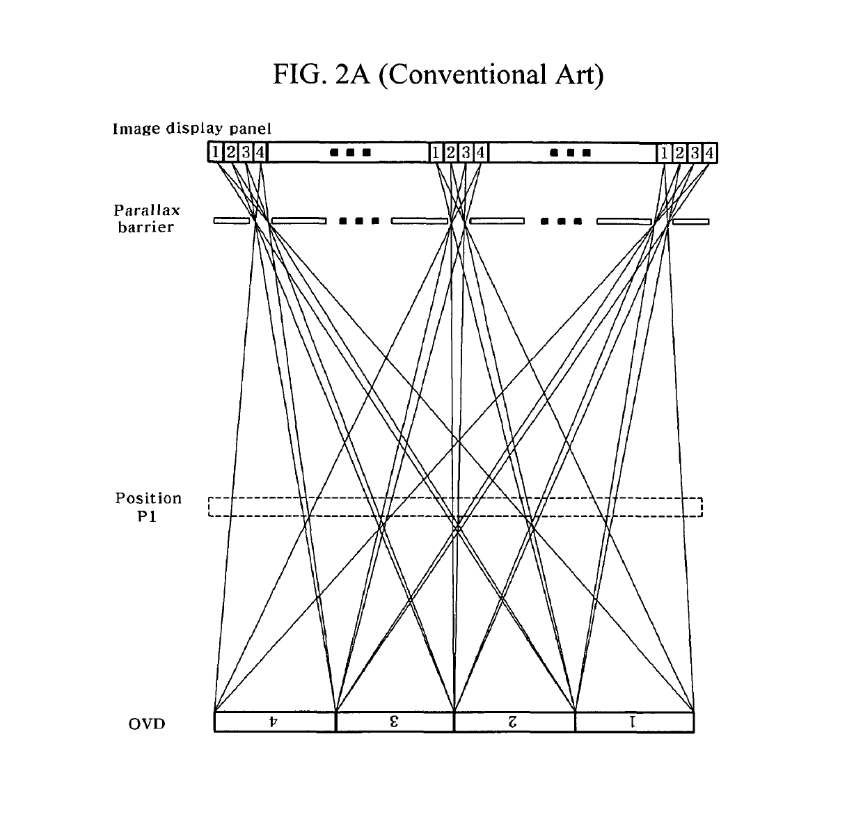
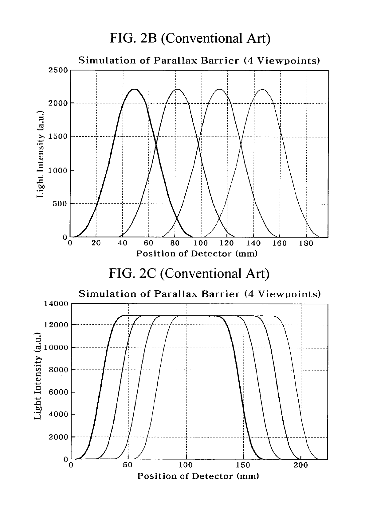
Third, in conventional autostereoscopic 3D image display devices, only a viewer who is located at a specific position (optimum viewing position) away from an image display device can view a clear 3D image. Consequently, when a viewer moves in a depth direction, the viewer cannot view a 3D image normally. This will now be described with reference to FIGS. 2A to 2D.

Method used


Image

  • Autostereoscopic three-dimensional image display device using time division
  • Autostereoscopic three-dimensional image display device using time division
  • Autostereoscopic three-dimensional image display device using time division

Examples


Embodiment Construction

[0040]Exemplary embodiments of the present invention will be described in detail below with reference to the accompanying drawings. While the present invention is shown and described in connection with exemplary embodiments thereof, it will be apparent to those skilled in the art that various modifications can be made without departing from the spirit and scope of the invention.

[0041]FIG. 3 is a conceptual diagram for describing a multi-viewing point 3D image display device using a line source according to an exemplary embodiment of the present invention.

[0042]Referring to FIG. 3, the 3D image display device includes: an image display panel that provides at least two viewing points to display a 3D image; and a backlight that is disposed to be separated by a certain distance from a rear surface of the image display panel. The backlight includes a plurality of line sources (hereinafter referred to as a first line source set), and a second line source set that includes a plurality of l...


PUM


Abstract

An autostereoscopic 3D image display device using time division is provided. The image display device includes a backlight, an image display panel, a controller, and a viewer position tracking system. The backlight includes a plurality of line sources which are disposed at certain intervals. The image display panel displays a 3D image. The controller controls the backlight and a viewing point image of the image display panel. The viewer position tracking system determines a pupil position of a viewer and transfers position information to the controller. The image display panel provides two or more viewing points. The line sources configure two or more line source sets that are separately driven at the same time. The two or more line source sets are sequentially driven.

Description

CROSS-REFERENCE TO RELATED APPLICATION[0001]This application claims priority to and the benefit of Korean Patent Application No. 2012-0005338, filed on Jan. 17, 2012, the disclosure of which is incorporated herein by reference in its entirety.BACKGROUND1. Field of the Invention[0002]The present invention relates to an autostereoscopic three-dimensional (3D) image display device, and more particularly, to an autostereoscopic 3D image display device that forms a viewing zone by using a plurality of line sources without using an optical plate such as a lenticular lens or a parallax barrier, and alternately drives two or more line source sets within an image-sticking time through a time division scheme, thus having enhanced resolution compared to the existing scheme.2. Discussion of Related Art[0003]General autostereoscopic 3D image display devices form a viewing zone by using an optical plate such as a lenticular lens or a parallax barrier. In this case, a viewer separately views a lef...

Claims


Application Information

Patent Timeline
Patent Type & Authority Patents(United States)
IPC IPC(8): G09G3/34H04N13/366H04N13/32
CPCG09G3/34H04N13/366H04N13/32G02B30/00
Inventor KIM, SUNG KYUYOON, KI HYUK
Owner SAMSUNG ELECTRONICS CO LTD
Learn More