Trace design for reduced visibility in touch screen devices

a touch screen device and trace design technology, applied in the input field, can solve the problems of affecting the display more, rendering simple size reduction an ineffective solution, and affecting the display

Inactive Publication Date: 2012-09-27
SYNAPTICS INC
View PDF11 Cites 108 Cited by
  • Summary
  • Abstract
  • Description
  • Claims
  • Application Information

AI Technical Summary

Benefits of technology

[0006]An input device having a plurality of low-visibility sensor electrodes and method for using the same are provided. In one embodiment, an input device includes a display device and a plurality of sensor electrodes disposed over the display device. The sensor electrodes are configured to sense objects in a sensing region of the input device. The sensor electrodes include a plurality of spaced apart conductive traces, each conductive trace having a diameter less than about 10 um. The conductive traces are disposed such that the conductive traces form a moiré pattern with the display device, wherein said moiré pattern comprises a spatial frequency greater than about 10 cycles per centimeter.
[0007]In another embodiment, an input device includes a display device and a sensing device. The sensing device has a plurality of first sensor electrodes and a plurality of second sensor electrodes, and is configured to sense objects in a sensing region adjacent the displace device. At least one of the first sensor electrodes and the second sensor electrodes comprise conductive traces having a diameter less than about 10 um. The conductive traces are disposed such that the conductive traces form a moiré pattern with the display device, wherein said moiré pattern comprises a spatial frequency greater than 10 cycles per centimeter.
[0008]In yet another embodiment, an input device includes a plurality of sensor electrodes disposed over a display device. The display device includes a plurality of pixels having a first orientation and second orientation orthogonal to the first orientation. The sensor electrodes are configured to sense an object in a sensing region of the input device, wherein the sensor electrodes comprise a plurality of spaced apart conductive traces. Each conductive trace has a diameter less than about 10 um. The conductive traces are oriented relative to plurality of pixels form a moiré pattern with the display device, wherein said moiré pattern comprises a pitch in a direction parallel to the first orientation smaller than the pitch of 3 cycles of pixels.

Problems solved by technology

Certain patterns interfere with the display more than others.
Cost effective processing precludes making the conductive traces so small that they cannot be seen under any condition, rendering simple size reduction as an ineffective solution.

Method used


Image

  • Trace design for reduced visibility in touch screen devices
  • Trace design for reduced visibility in touch screen devices
  • Trace design for reduced visibility in touch screen devices

Examples


Embodiment Construction

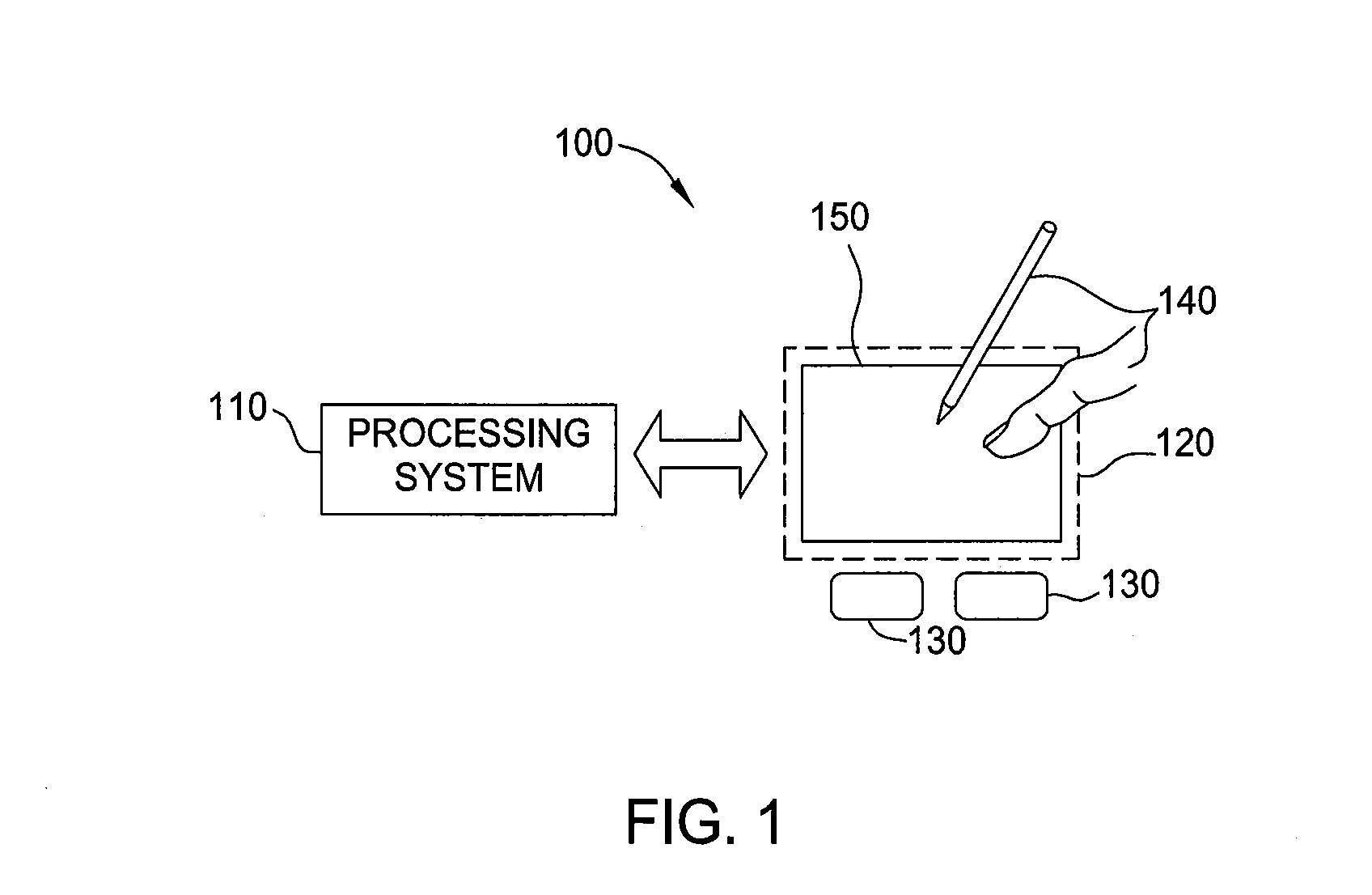
[0018]The following Description of Embodiments is merely provided by way of example and not of limitation. Furthermore, there is no intention to be bound by any expressed or implied theory presented in the preceding technical field, background, brief summary or the following detailed description. Various embodiments of the present invention provide input devices and methods that facilitate improved usability of a touch screen device.

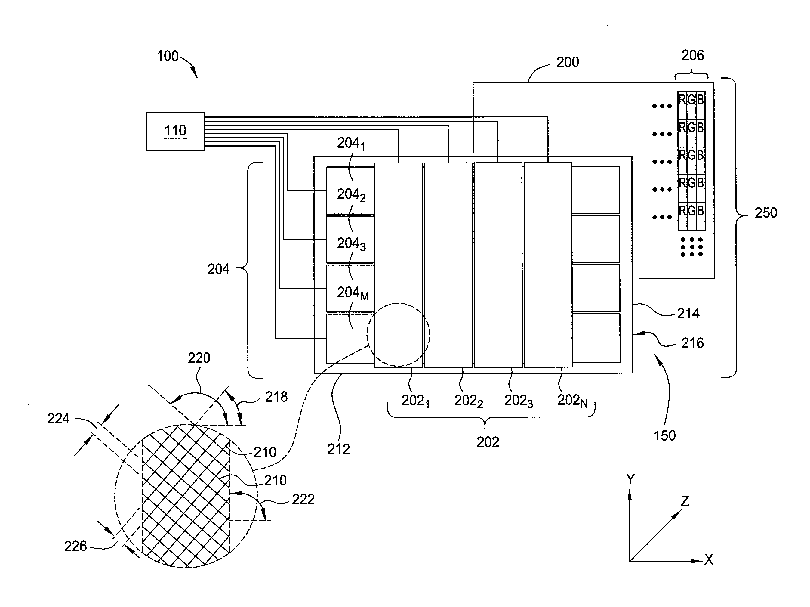
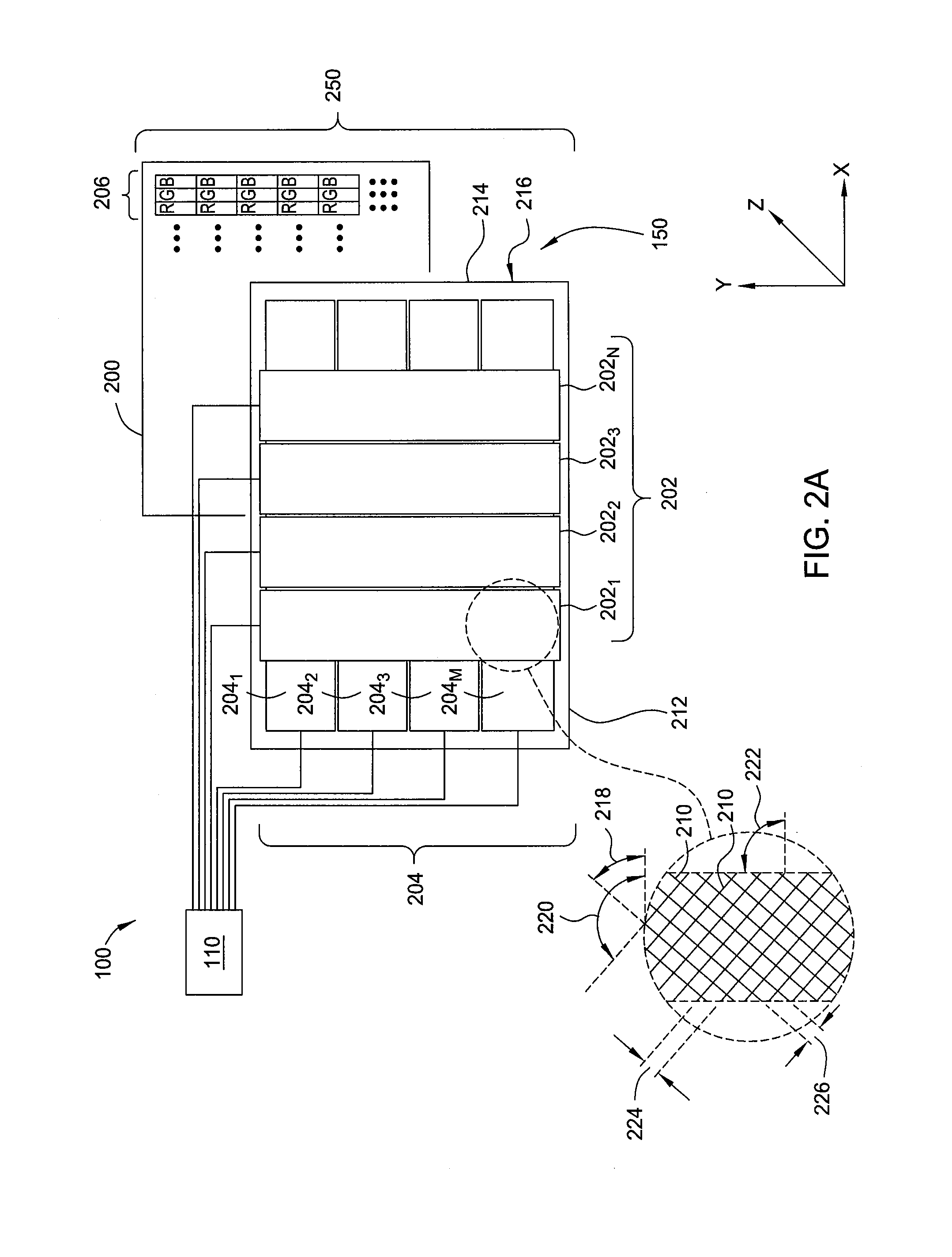
[0019]In various embodiments, an input device is formed from conductive traces (i.e., micro-traces) arranged at an angle and periodicity such that the traces are substantially invisible, thus allowing larger assemblies of small traces to form sensor elements that do not substantially diminish the quality of light transmission through the input device. Advantageously, the low-visibility traces can be utilized to form sensor elements in virtually any arbitrary shape, size or orientation, thereby allowing the design of the sensor elements to focus on device...


PUM


Abstract

An input device having a plurality of low-visibility sensor electrodes and method for using the same are provided. In one embodiment, an input device includes a display device and a plurality of sensor electrodes disposed over the display device. The sensor electrodes are configured to sense objects in a sensing region of the input device. The sensor electrodes include a plurality of spaced apart conductive traces, each conductive trace having a diameter less than about 10 um. The conductive traces are disposed such that the conductive traces form a moiré pattern with the display device, wherein said moiré pattern comprises a spatial frequency greater than about 10 cycles per centimeter.

Description

CROSS REFERENCE TO RELATED APPLICATIONS[0001]This application claims benefit of U.S. Provisional Patent Application Ser. No. 61 / 466,792, filed Mar. 23, 2011, and titled “TRACE DESIGN FOR REDUCED VISIBILITY IN TOUCH SCREEN DEVICES”, which is incorporated by reference in its entirety.FIELD OF INVENTION[0002]Embodiments of the invention generally relate to an input device having a plurality of low-visibility sensor electrodes and method sensing an input object using the same.BACKGROUND[0003]Input devices including proximity sensor devices (also commonly called touchpads or touch sensor devices) are widely used in a variety of electronic systems. A proximity sensor device typically includes a sensing region, often demarked by a surface, in which the proximity sensor device determines the presence, location and / or motion of one or more input objects. Proximity sensor devices may be used to provide interfaces for the electronic system. For example, proximity sensor devices are often used ...

Claims


Application Information

Patent Timeline
Patent Type & Authority Applications(United States)
IPC IPC(8): G06F3/041
CPCG06F2203/04112G06F3/044G06F3/0412G06F3/0443G06F3/0446
Inventor MACKEY, BOB LEE
Owner SYNAPTICS INC
Why Eureka
Try Eureka