Rotary roaster

Inactive Publication Date: 2012-10-04
TALL & STOUT INDAL CORP
5 Cites 5 Cited by

AI-Extracted Technical Summary

Problems solved by technology

However, the food tends to be rent or become soupy because of being continuously stirred by the stirrer.
Further, piecemeal food i...

Benefits of technology

[0009]An advantage of the invention is structural simplification and stabilization by means of mounting the driving mechanism down...

Abstract

The rotary roaster includes a housing, a pot and a driving mechanism. The housing has a base. The driving mechanism is disposed on the base and has a rotary tray for being placed by the pot so that the pot is rotated by the rotary tray.

Application Domain

Roasting apparatusBaking plants

Technology Topic

EngineeringMechanical engineering

Image

  • Rotary roaster
  • Rotary roaster
  • Rotary roaster

Examples

  • Experimental program(1)

Example

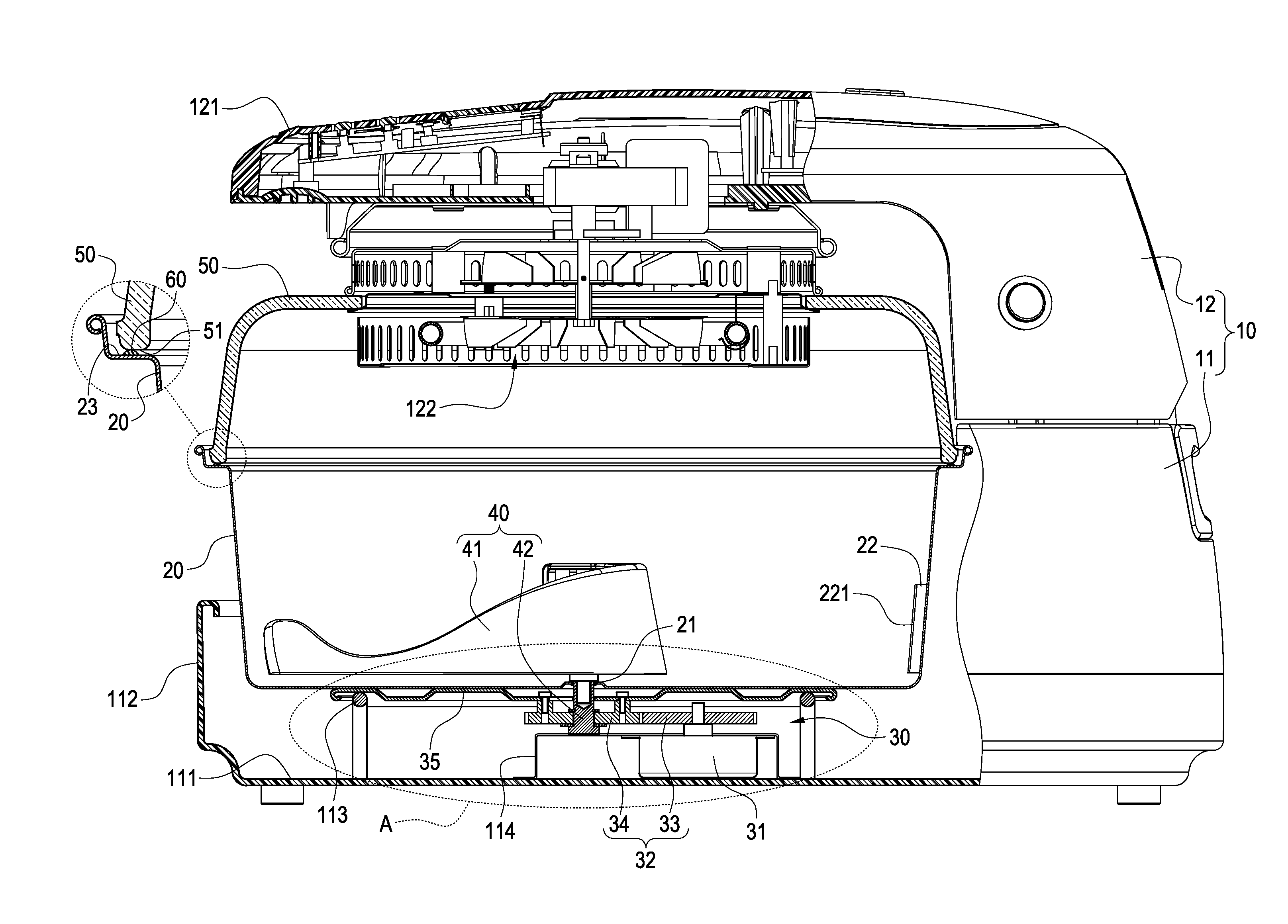
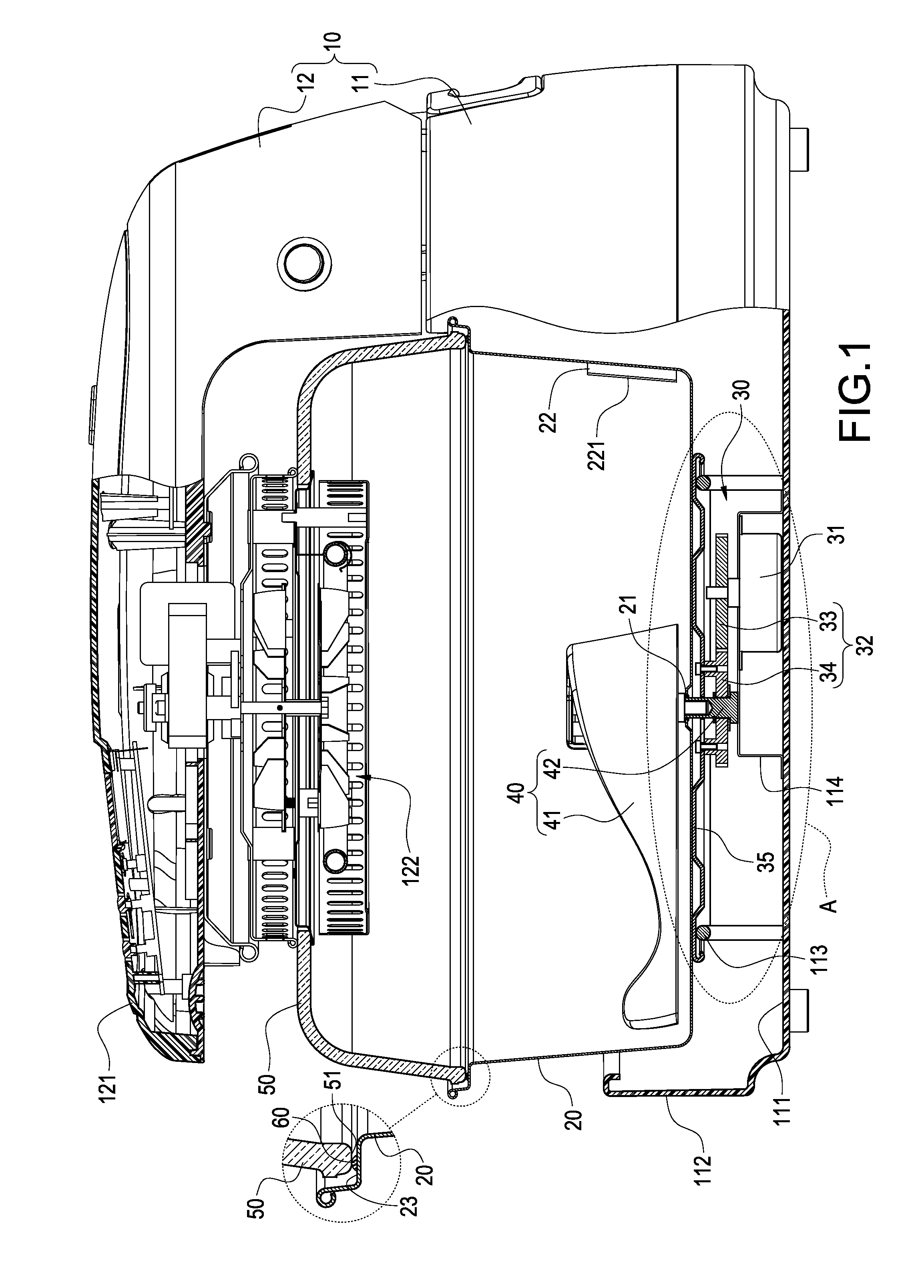
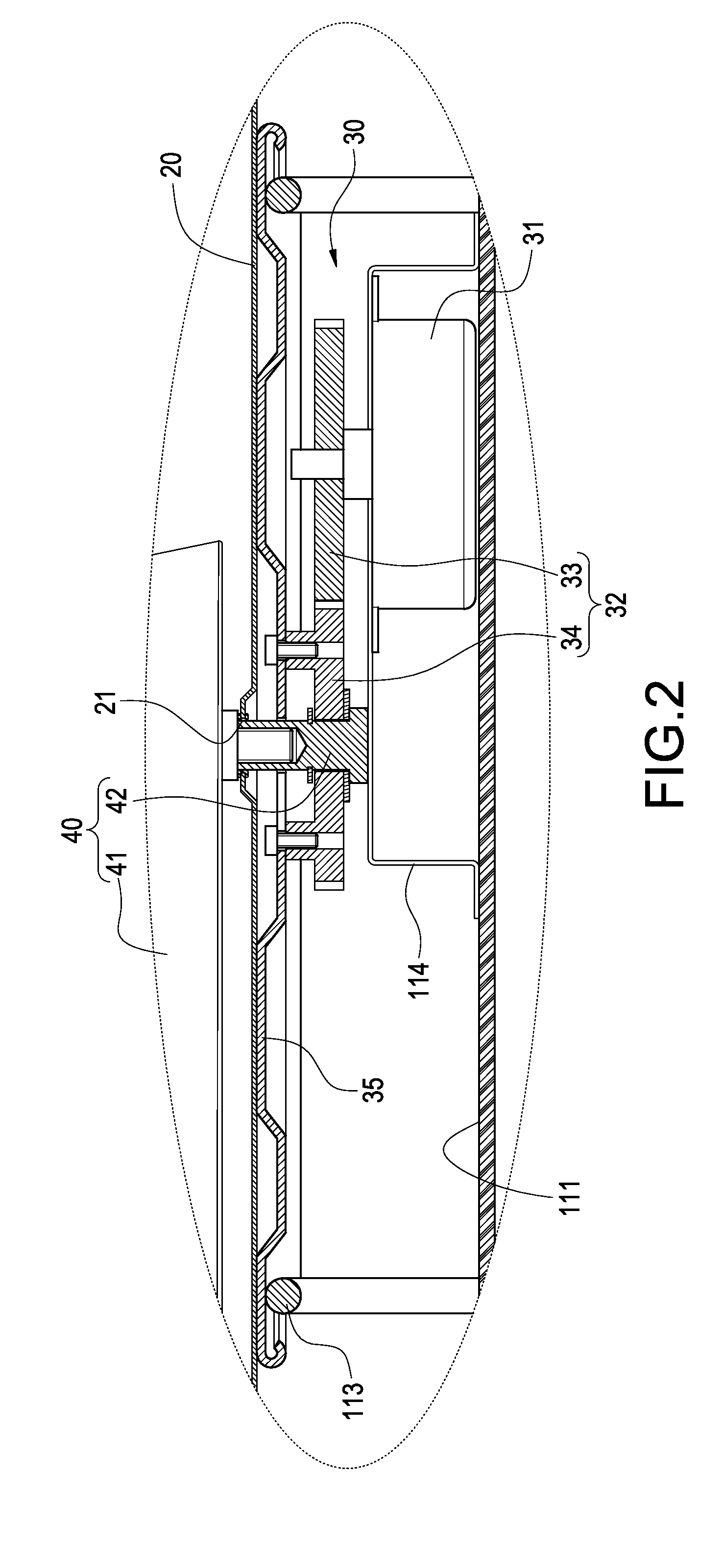
[0017]Please refer to FIGS. 1-4. The roaster of the invention includes a housing 10, a pot 20 and a driving mechanism 30.
[0018]The housing 10 includes a base 11 and a liftable arm 12. The base 11 has a bottom 111 and a wall 112 extending around the bottom 111. A supporting loop 113 and seat 114 are separately fixed on the bottom 111. One end of the liftable arm 12 is pivotally connected at one side of the base. The liftable arm 12 may be upwards opened and downwards closed. The liftable arm 12 includes an L-shaped arm 121 and a heater 122 mounted under the L-shaped arm 121.
[0019]The pot 20 is made of transparent material. The pot 20 is placed on the supporting loop 113 and surrounded by the wall 112. The pot 20 protrudes from the wall 112 so that food in the pot 20 is easy to be viewed. A through hole 21 is formed at the center of the pot 20. A blocker plate 22 is formed on the inside of the pot 20. The blocker plate 22 is formed with a bent flange 221 for preventing inside food from being spoiled by the blocker plate 22.
[0020]The driving mechanism 30 includes a motor 31, a gear set 32 and a rotary tray 35. The gear set 32 is composed of a first gear 31 and a second gear 34. The motor 31 is mounted on the seat 114. The spindle of the motor 31 is fixed to the first gear 33 and the second gear 34 is fixed to the rotary tray 35 by screws. The pot 20 is put on the rotary tray 35 and can be rotated with the rotary tray 35 driven by the motor 31 through the gear set 32.
[0021]The rotary roaster of the invention further includes a stirrer 40 composed of a blade 41 and a pin 42. The blade 41 is unrotably fixed in the pot 20. One end of the pin 42 is fixed to the seat 114 and the other end penetrates through the second gear 34, rotary tray 35 and through hole 21 and connects to the blade 41.
[0022]The rotary roaster further includes a cover 50 and a seal ring 60. The cover 50 is connected to the heater 122 in the liftable arm 12. Heat from the heater 122 is formed in the cover 50 on the pot 20. A bend portion 23 is formed on an upper edge of the pot 20. A flat portion 51 is formed on a lower edge of the cover 50. The flat portion 51 is put on the bend portion 23 and the seal ring 60 is sandwiched between the flat portion 51 and bend portion 23 for complete seal.
[0023]When the heater 122 is heating up, the pot 20 and rotary tray 35 is rotated by the motor 31 through the gear set 32 and the food in the pot 20 will be rotated with the pot 20. In the meantime, the rotating food will be stirred or mixed by the unrotatable blade 41 because of its blocking effect. Furthermore, the blocker plate 22 can cooperate with the blade 41 to sufficiently turn over the food. Thus the food in the pot 20 can be evenly and completely heated.
[0024]Please refer to FIGS. 5-7, which show another embodiment of the invention. In this embodiment, the pot 20 is directly driven by the motor 31. The stirrer 40 further includes a connecting rod 43. Two ends of the connecting rod 43 are fixed to the pin 42 fixed to the blade 41 and a frame of the heater 122 under the cover 50, respectively. Thus the blade 41 will not be rotated with the pot 20. This embodiment can perform the same function as the above embodiment.
[0025]It will be appreciated by persons skilled in the art that the above embodiments have been described by way of example only and not in any limitative sense, and that various alterations and modifications are possible without departure from the scope of the invention as defined by the appended claims.

PUM

no PUM

Description & Claims & Application Information

We can also present the details of the Description, Claims and Application information to help users get a comprehensive understanding of the technical details of the patent, such as background art, summary of invention, brief description of drawings, description of embodiments, and other original content. On the other hand, users can also determine the specific scope of protection of the technology through the list of claims; as well as understand the changes in the life cycle of the technology with the presentation of the patent timeline. Login to view more.

Similar technology patents

Electronic apparatus and display control method thereof

ActiveUS20160291850A1easily viewwell view quality and visual effect
Owner:HTC CORP

Game system, game device, storage medium storing game program, and game process method

ActiveUS20120115602A1easily viewmore performance
Owner:NINTENDO CO LTD

Classification and recommendation of technical efficacy words

Why Eureka
Try Eureka