Load-Limiting Devices

a technology of load-limiting devices and clamping rods, which is applied in the direction of traffic restrictions, manufacturing tools, roads, etc., can solve the problems of net recoil, weak link described above, and inability to completely guarantee the reliability of such stitching, so as to achieve elongation and energy absorption, and slow down the effect of falling

Inactive Publication Date: 2012-10-04
QINETIQ LTD
View PDF6 Cites 4 Cited by
  • Summary
  • Abstract
  • Description
  • Claims
  • Application Information

AI Technical Summary

Benefits of technology

[0010]Devices according to the invention may however also have utility in various other applications where it is desired to limit the tensile load in a system and absorb energy by elongation prior to release from the system. Examples may include the release of tethered animals when a sufficient pull is applied e.g. in the event of fire, or the protection from overload of rigging or sail attachments on sailing boats. Such devices could also be modified to permit elongation and energy absorption when subject to a threshold loading but not ultimate release at all if a terminal portion of the coil is welded or otherwise made fast with an adjacent turn to prevent it unwinding completely. This may be useful e.g. for a fall arrest system for persons working at height where unwinding of the coil could break and slow a fall if connected between a safety rope and a harness but not allow detachment from the rope at the end of its elongation.

Problems solved by technology

In practice it has been found that the kinds of weak links described above are not entirely reliable in that there can be wide variations in the tensile load at which each type actually fails.
In the case of weak stitching it is difficult to achieve sufficiently tight manufacturing tolerances and the strength of such stitching can also decrease with age.
It has also been found that breakage of the plastics ties during deployment of the net can sometimes cause the net to recoil so that it does not thereafter lie evenly on the ground.

Method used


Image

  • Load-Limiting Devices
  • Load-Limiting Devices
  • Load-Limiting Devices

Examples


Embodiment Construction

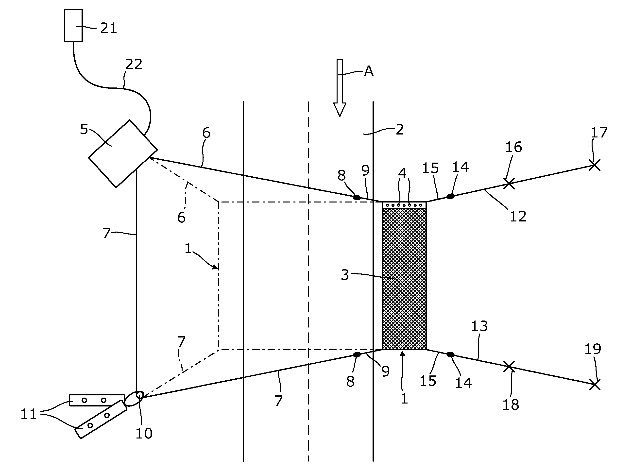
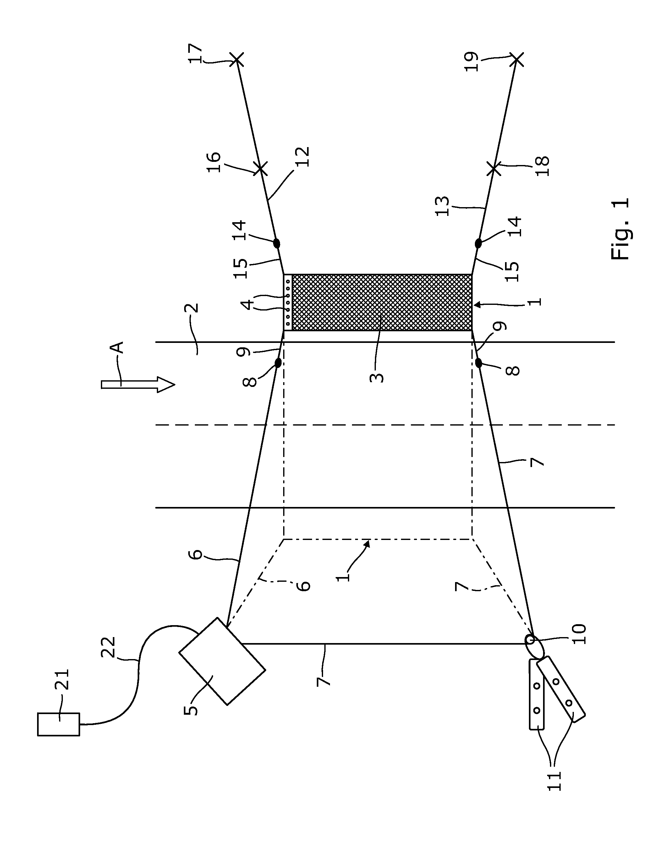
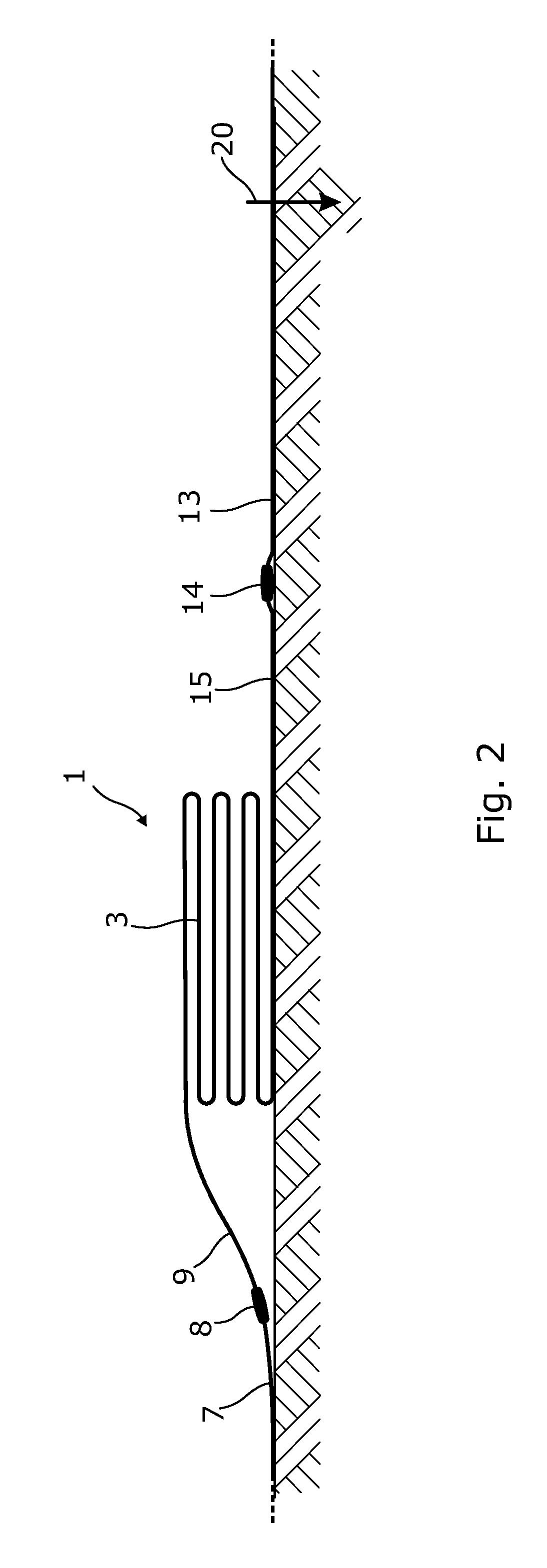
[0020]With reference to FIG. 1 there is shown a vehicle arresting device 1 of the kind more fully described and illustrated in U.S. Pat. No. 7,862,251 in a folded condition to one side of a roadway 2 and ready to be deployed in the path of a target vehicle (not shown) approaching in the direction of the arrow A. The device 1 comprises a net 3 of rectangular planform intended to lie flat across the roadway when deployed and equipped with one or more rows of barbed spikes 4 along its leading edge (in the sense of the direction of approach A). It is folded laterally upon itself in concertina fashion as indicated in FIG. 2 (from which the spikes 4 are omitted for ease of illustration and in which the successive leaves of the folded net are shown spaced from each other in the vertical direction also for ease of illustration). In use, when a vehicle encounters the deployed device 1 (the device being then in the position notionally illustrated in broken line in FIG. 1) from the direction o...


PUM


Abstract

A load-limiting device is formed from a length of wire with a coil at each end defining eyes by which the device can be connected into a system adapted to be loaded in tension. The coils are of different diameter and the larger diameter coil is adapted to unwind by plastic deformation of the wire when the device is subject to a tensile load of a predetermined magnitude. The use of such devices in a system for deploying a vehicle arresting device across a roadway is also described.

Description

FIELD OF THE INVENTION[0001]The invention relates to load-limiting devices and more particularly to a device adapted to limit the tensile load within a system in which it is incorporated.BACKGROUND OF THE INVENTION[0002]The invention has been developed specifically for limiting tensile loads within a system such as described in U.S. patent application Ser. No. 12 / 992507 for deploying a vehicle arresting device of the kind described in U.S. Pat. No. 7862251, the contents of which are incorporated herein by reference. The vehicle arrester comprises a flexible substrate in the form of a net and with an array of spikes along its leading edge, which is deployed by pulling it across a road, from a folded condition on one side of the road, to lie flat on the ground in the path of a target vehicle. This is accomplished by cables attached to one side edge of the net which are wound in by a winch located on the opposite side of the road, while the other side edge of the net is anchored to the...

Claims


Application Information

Patent Timeline
Patent Type & Authority Applications(United States)
IPC IPC(8): E01F13/12F16B1/00
CPCY10T403/27E01F13/12
Inventor DANDY, PHILIP JOHNBANKS-FEAR, DAVID PETER
Owner QINETIQ LTD
Why Eureka
Try Eureka