Electrical resource controller

Active Publication Date: 2012-10-04
THE UNITED STATES OF AMERICA AS REPRESENTED BY THE SECRETARY OF THE NAVY
View PDF4 Cites 21 Cited by
  • Summary
  • Abstract
  • Description
  • Claims
  • Application Information

AI Technical Summary

Benefits of technology

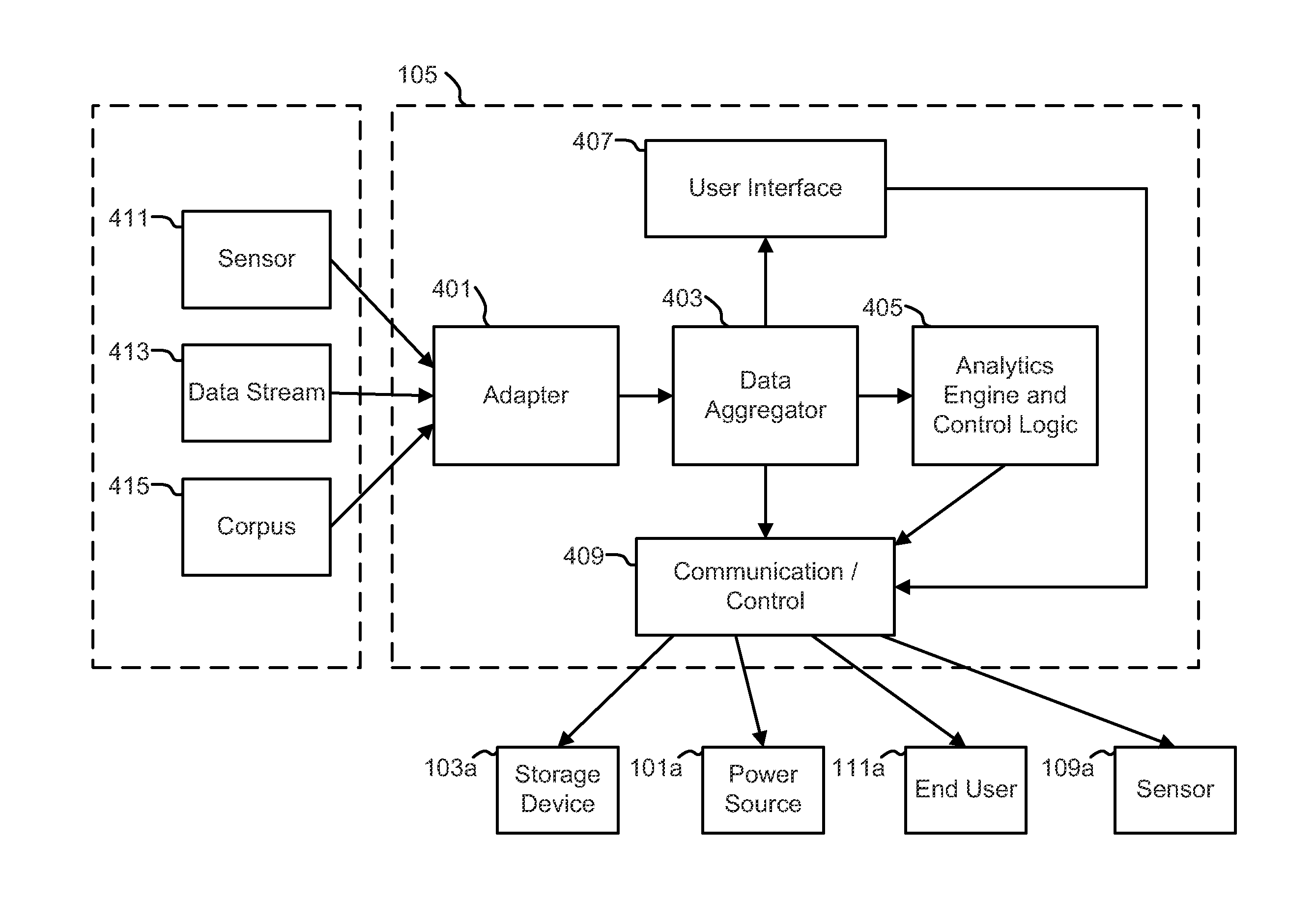
[0004]In an additional exemplary embodiment of the present disclosure, the controller of the electrical system utilizes an analytics engine to make power planning decisions, the analytics engine comprising first, second, and third plurality of processing sequences, wherein the first plurality of processing sequences is adapted to perform interface activities with a plurality of potential disruption event databases, the second plurality of processing sequences is adapted to perform business analytics processing based on a plurality of business analytics data, and the third plurality of processing sequences is adapted to produce a plurality of outputs comprising first, second, and third outputs. The potential disruption event databases comprise data from sensors, command and control facilities, weather sources including tsunami reporting, and other real time event reporting databases including national security, civil defense, weather, and intelligence threat databases. The plurality of business analytics data comprises network component data, network data, node power requirements, node chain power consumption data, equipment or function priority data, location data, power grid data, supported entity/mission data, predicted power disruption impact data, power disruption cost data, threat to life indicator, threat to property indicator, threat to critical infrastructure indicator, threat to critical subsystem indicator, lost opportunity cost from disruption data, and predicted time of disruption data. The first output comprises a network disruption prediction report comprising a list of network nodes, missions, locations or other elements which are presently at risk or are predicted to be at risk within 72 hours or less based on outputs from the first, second, and third processing sequences, the plurality of business analytics data, the data from the potential disruption event database, and data provided by the at least one device sensor. The second output comprises a list and at least one network diagram showing a plurality of proposed network disruption prevention actions determined based on: outputs from the first, second, and third processing sequences, the plurality of business analytics data, the data from the potential disruption event database, and data provided by the at least one device sensor. The third output comprises a critical path listing showing critical elements, nodes, or links from the first output with a proposed corrective action, including corrective actions which are automatically implemented by the electrical system.
[0005]In another exemplary

Problems solved by technology

In other electrical systems, a location may have requirements in order to sustain electrical operations while an electrical grid is offline or operating at a limited capacity (i.e., insufficient for demand).
Additionally, the deployment of a number of sm

Method used


Image

  • Electrical resource controller
  • Electrical resource controller
  • Electrical resource controller

Examples


Example

[0015]Corresponding reference characters indicate corresponding parts throughout the several views. Although the drawings represent embodiments of various features and components according to the present disclosure, the drawings are not necessarily to scale and certain features may be exaggerated in order to better illustrate and explain the present disclosure. The exemplification set out herein illustrates embodiments of the invention, and such exemplifications are not to be construed as limiting the scope of the invention in any manner.

DETAILED DESCRIPTION OF THE DRAWINGS

[0016]For the purposes of promoting an understanding of the principles of the invention, reference will now be made to the embodiments illustrated in the drawings, which are described below. The embodiments disclosed below are not intended to be exhaustive or limit the invention to the precise form disclosed in the following detailed description. Rather, the embodiments are chosen and described so that others skil...


PUM


Abstract

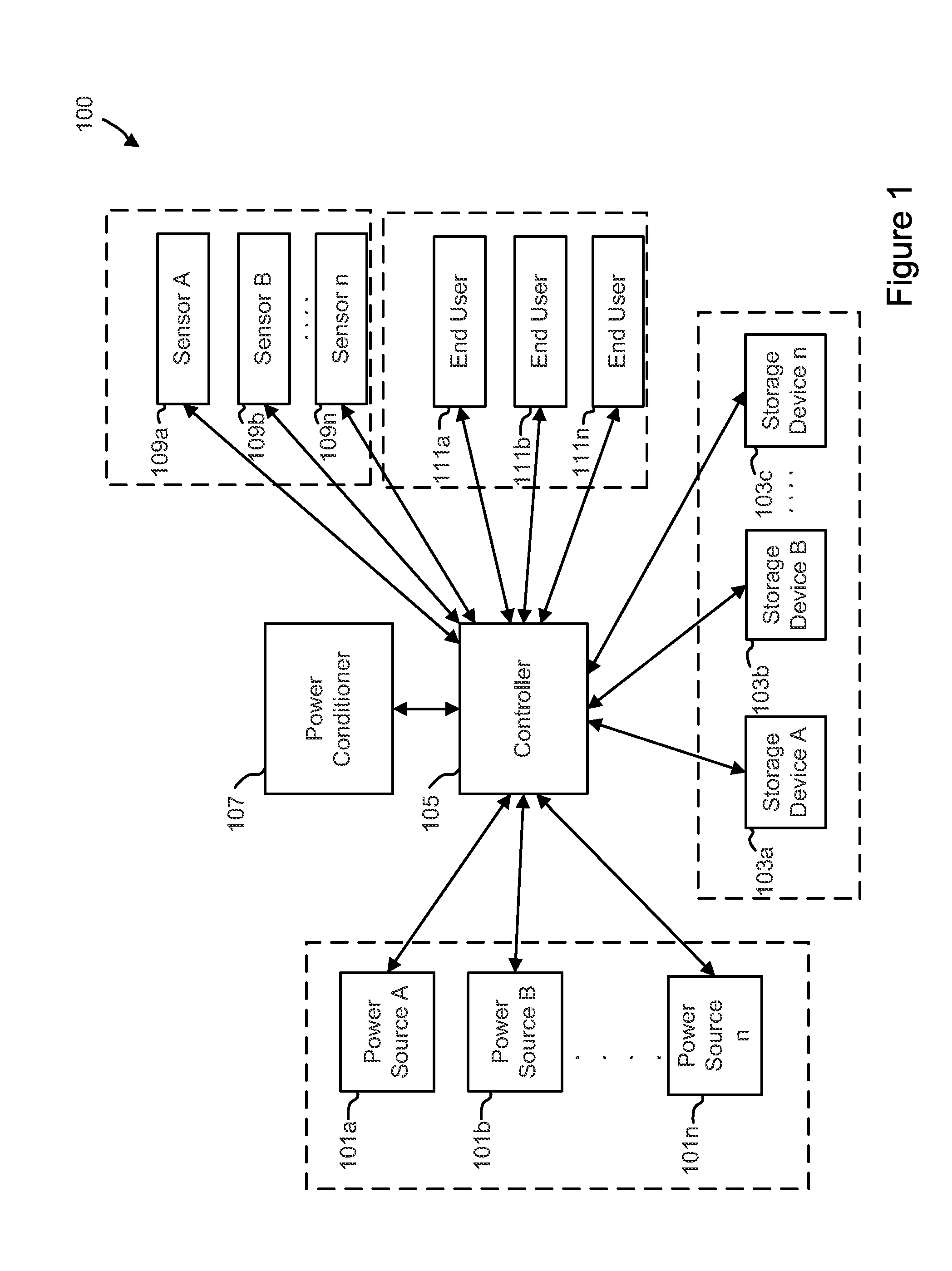
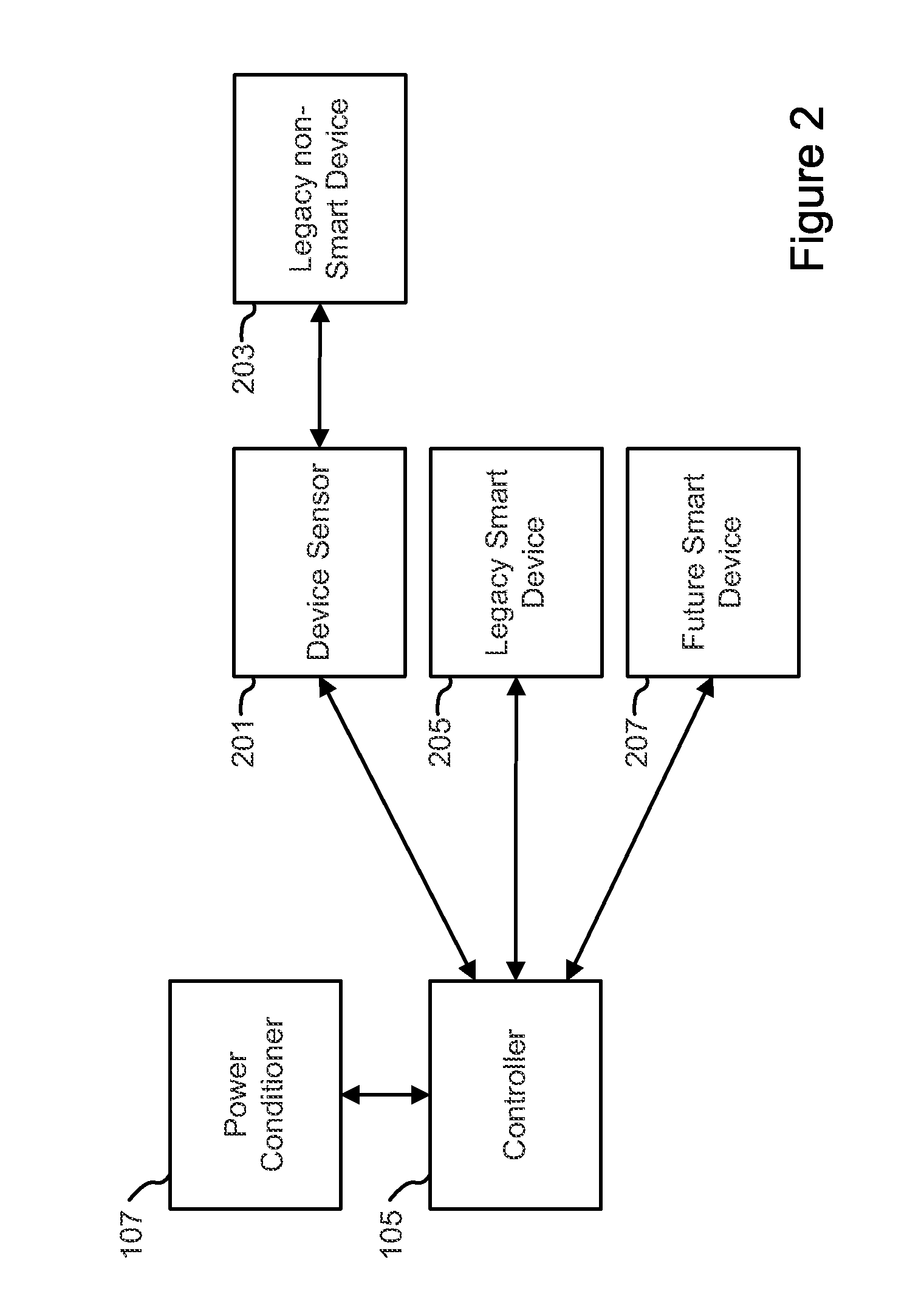
In an exemplary embodiment of the present disclosure, an electrical system is provided. The system comprises a controller including a plurality of machine implemented processing sequences. The electrical system also includes a plurality of sensors configured to receive input related to the environmental conditions of the environment surrounding the plurality of sensors and transmit the input to the controller, at least one power source in electrical communication with the controller. The electrical system further includes at least one storage device in electrical communication with the controller, and at least one device sensor in communication with an end user. The at least one device sensor includes memory, and the memory includes priority information regarding the priority of a device associated with the at least one device sensor. The at least one device sensor is operable to transmit information to the controller.

Description

STATEMENT REGARDING FEDERALLY SPONSORED RESEARCH OR DEVELOPMENT[0001]The invention described herein was made in the performance of official duties by employees of the Department of the Navy and may be manufactured, used and licensed by or for the United States Government for any governmental purpose without payment of any royalties thereon.BACKGROUND OF THE INVENTION[0002]The present invention relates generally to devices to control and distribute electricity. In many electrical systems, remote location may not be in communication with local, regional, national, or international electrical grids. In other electrical systems, a location may have requirements in order to sustain electrical operations while an electrical grid is offline or operating at a limited capacity (i.e., insufficient for demand). Additionally, the deployment of a number of small generators to fulfill electrical needs on a small scale may be inefficient, as the small generators may not be as robust as a fewer num...

Claims


Application Information

Patent Timeline
IPC IPC(8): G06Q10/04G06F1/26
CPCG06Q50/06G06Q10/06
Inventor SCHNEIDER, JOHN FELIXBROWN, CHRISTOPHER ALLEN
Owner THE UNITED STATES OF AMERICA AS REPRESENTED BY THE SECRETARY OF THE NAVY
Why Eureka
Try Eureka