

Cold box design providing secondary containment
a technology of secondary containment and cold box, which is applied in the direction of transportation and packaging, liquefaction, lighting and heating apparatus, etc., can solve the problems of not being suitable for cryogenic temperature exposure, being manufactured from carbon steel material, and not providing significant protection from external fires or secondary leakage protection
- Summary
- Abstract
- Description
- Claims
- Application Information
AI Technical Summary
Benefits of technology
Problems solved by technology
Method used
Image

Examples
Embodiment Construction
[0016]Reference will now be made in detail to embodiments of the invention, one or more examples of which are illustrated in the accompanying drawings. Each example is provided by way of explanation of the invention, not as a limitation of the invention. It will be apparent to those skilled in the art that various modifications and variation can be made in the present invention without departing from the scope or spirit of the invention. For instances, features illustrated or described as part of one embodiment can be used in another embodiment to yield a still further embodiment. Thus, it is intended that the present invention cover such modifications and variations that come within the scope of the appended claims and their equivalents.
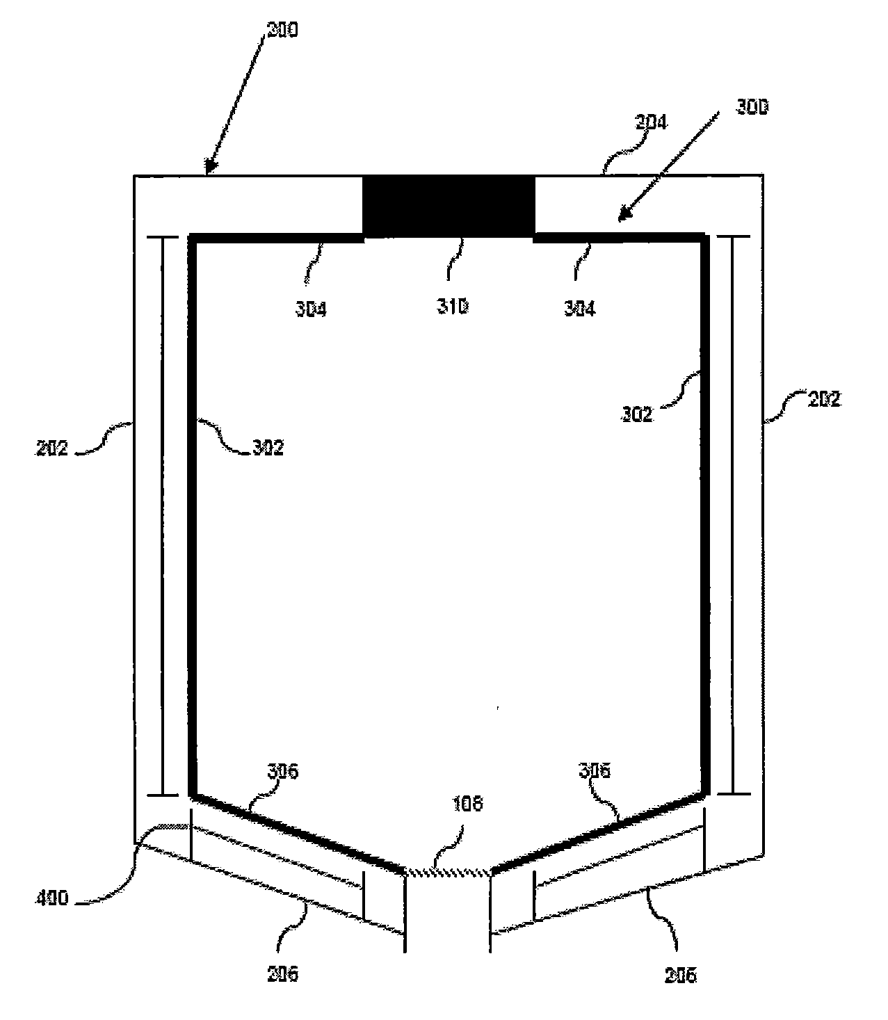
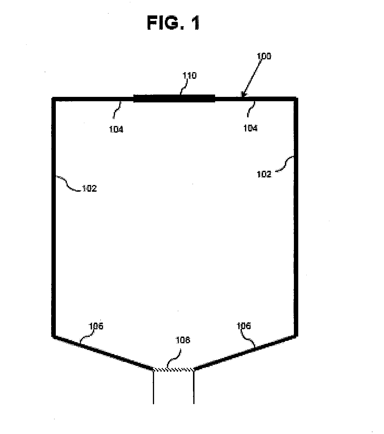
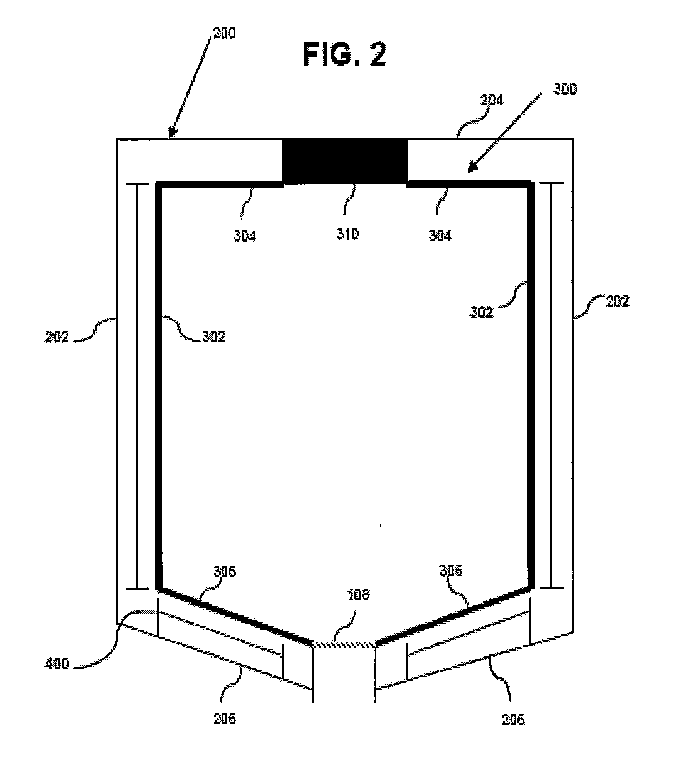
[0017]FIG. 1 depicts a primary enclosure defining an internal volume. The primary enclosure can function as a thermal insulator capable of containing equipment operating at cryogenic temperatures. For instance, the primary enclosure can be a cold bo...
PUM
 Abstract
Description
Claims
Application Information