
Method of propulsion

a technology of propulsion and propellant, applied in the direction of machines/engines, dynamo-electric machines, electrical apparatus, etc., can solve the problems of major disadvantages and limitations of current technology, and the need for propellant for propulsion

Inactive Publication Date: 2012-10-25
ARIEL HAROLD
View PDF19 Cites 16 Cited by
  • Summary
  • Abstract
  • Description
  • Claims
  • Application Information

AI Technical Summary

Problems solved by technology

Nevertheless, the requirement of propellant for propulsion is the major disadvantage and the major limitation of the current technology.

Method used


Image

  • Method of propulsion
  • Method of propulsion
  • Method of propulsion

Examples


Embodiment Construction

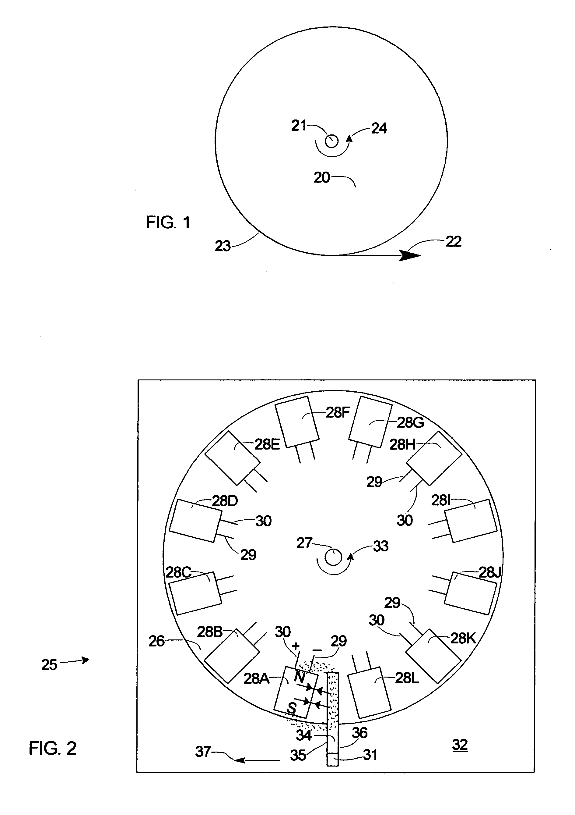
[0029]FIG. 1 illustrates a principle of practice in the operation of the invention comprising a rotatable circular disk 20 pivotally mounted for rotation on an axle 21. A force 22 tangent to the periphery 23 of the disk 20 is a motive force that impresses upon the disk 20 a torque that generates the rotation 24 about the axle 21.

Figs. 2-5

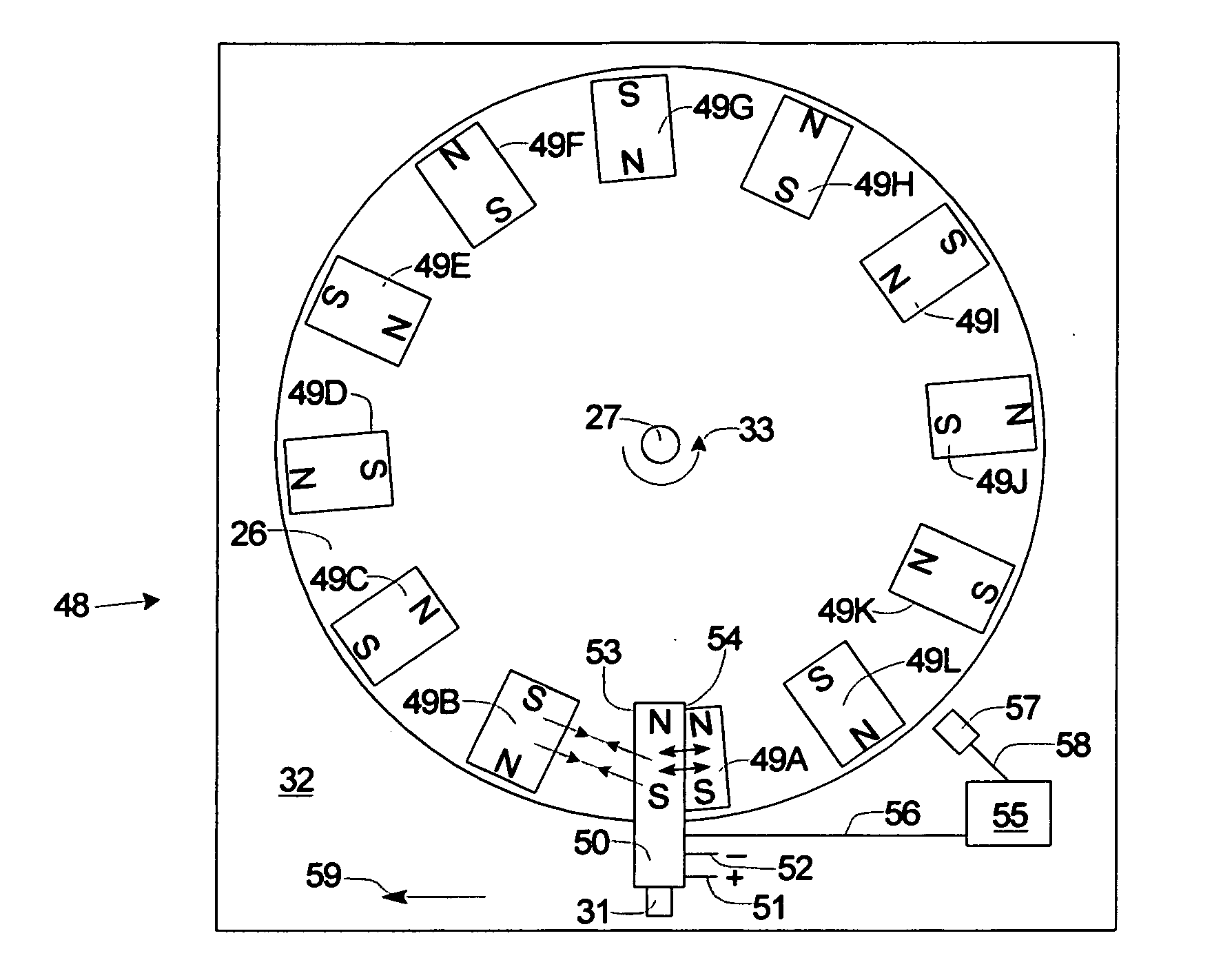
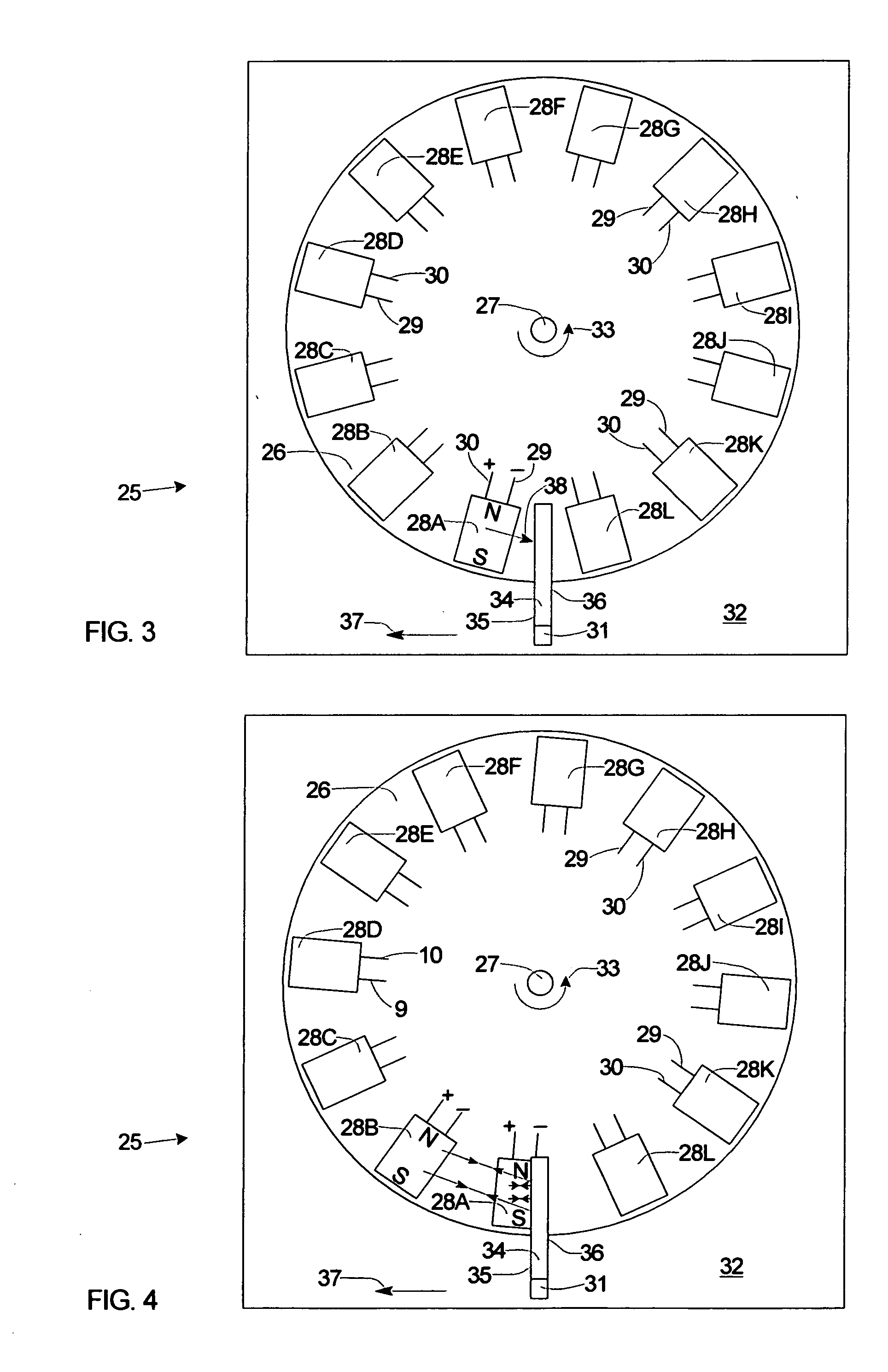
[0030]To illustrate an embodiment of the method of propulsion, FIGS. 2-5 show the schematics of an electron magnetic drive 25 comprising a rotor 26 pivotally mounted for rotation on a central axle 27. Mounted on the rotor 26 is a plurality of rotor electromagnets 28A-28L, and each of the electromagnets 28A-28L has power input terminals 29 and 30. A stator support member 31 mounted on a base frame 32 provides mounting support for a stator 34. An arrow indicates the counterclockwise direction of a rotation 33 of the rotor 26 about the axle 27. The stator 34, made of a magnetic permeable material comprises a leading side 35 facing the oncoming traffic ...


PUM


Abstract

One embodiment of the new method of propulsion is an electron magnetic drive with an array of rotor electromagnets (28A-28L) operating in the non inertial frame of reference produced by the rotation (33) of the rotor (26); linked by a magnetic field from the electromagnets (28A-28L) to the inertial frame of reference of the stationary stator electromagnet (40); generate a propulsive reaction force (45) in accordance with Newton's third law of motion. The electromagnets (28A-28L) mounted on the rotor (26), when energized for a time interval generate a magnetic field that engages the magnetic field of the energized stator electromagnet (40). The magnetic field engagement produces magnetic forces of attraction and repulsion with the like and unlike magnetic polarities of the energized stationary electromagnet (40) and the corresponding energized electromagnet (28A-28L) in the rotor (26).

Description

BACKGROUND [0001]1. Field[0002]A method that employs; the magnetic forces in the magnetic field linking Newton's third law of motion in two frames of reference to produce a reaction propulsion force.[0003]2. Prior Art[0004]All of the present propulsion technology is based on Newton's third law of motion; “for every action there is an equal and opposite reaction”. Rockets carry their own propellant and expel it through a nozzle to produce the reaction force of propulsion. Unlike a rocket that carries its own propellant; a jet engine takes in propellant from the surrounding atmosphere, mixes it with fuel, and accelerate it through the jet engine's nozzle. A propeller utilizes; a mass of air or water from the environment and accelerate it to produce propeller thrust. An internal combustion engine with a drive train, giving power to the wheels of a land driven motor vehicle employs the traction with the ground for propulsion. The ground serves as the propellant. All these prime movers o...

Claims


Application Information

Patent Timeline
Patent Type & Authority Applications(United States)
IPC IPC(8): H02K7/02
CPCH02K7/06F03G7/10H02K57/006H02K53/00H02K99/20
Inventor ARIEL, HAROLD
Owner ARIEL HAROLD
Learn More