Shake correction device, shake correction method, and imaging apparatus

a shake correction and shake technology, applied in the field of shake correction devices, shake correction methods and imaging apparatuses, can solve the problems of difficult control of effective elimination of shake, deterioration of camera shake correction performance,

Active Publication Date: 2012-11-01
SONY CORP
View PDF0 Cites 2 Cited by
  • Summary
  • Abstract
  • Description
  • Claims
  • Application Information

AI Technical Summary

Benefits of technology

[0011]It is desirable to provide a shake correction device, a shake correction method and an imaging apparatus, which is capable of performing suitable shake correction using a correction area effectively.
[0012]According to an embodiment of the present invention, there is provided a shake correction device including: a shake detection unit detecting shake so as to generate a shake detection signal; a driving unit displacing a relative positional relationship between a lens unit and an imaging device with respect to an optical axis so as to displace the position on the imaging surface of an optical image formed on an imaging surface of the imaging device; a displacement detection unit detecting a displacement state of the correction lens unit or the imaging device; a filter processing unit performing a filter process of the shake detection signal; and a correction control unit displacing the relative positional relationship between the lens unit and the imaging device according to the filter-processed shake detection signal so as to correct the shake of the optical image on the imaging surface generated by the shake detected by the shake detection unit, wherein the filter processing unit changes filter processing characteristics according to the displacement state detected by the displacement detection unit, and limits the shake correction of the optical image as the detected displacement state becomes close to a displacement limit.
[0013]In the embodiment of the present invention, the filter processing unit may limit a low frequency component of the shake detection signal as the displacement state becomes close to the displacement limit so as to limit the shake correction of the low frequency component. For example, the predetermined low frequency component of the shake detection signal is limited as the displacement state becomes close to the displacement limit so as to limit the shake correction of the low frequency component. The filter processing unit performs a high-pass filter process, and increases a cutoff frequency of the high-pass filter process as the displacement state becomes close to the displacement limit so as to limit the shake correction of the low frequency component having a lower frequency than the cutoff frequency. The filter processing unit sequentially reinforces the limit of the low frequency component when the displacement state is close to the displacement limit rather than a predetermined state and sequentially eases the limit when the displacement state is separated from the displacement limit rather than the predetermined state.
[0016]According to the embodiments of the present invention, the filter processing characteristics of the shake detection signal are changed according to the displacement state detected by the displacement detection unit, and the shake correction of the optical image is limited as the detected displacement state becomes close to the displacement limit. To this end, when the displacement state is separated from the displacement limit, the shake correction is performed using a correction area effectively, with respect to small shake or large shake such as when an image is picked up while walking. In addition, shake correction is limited as the displacement state becomes close to the displacement limit. For example, shake correction is performed with respect to small shake such as camera shake, shake correction is limited with respect to large shake such as when an image is picked up while walking, and the correction lens unit is prevented from colliding with the inside wall of a lens barrel. Accordingly, suitable shake correction can be performed using a correction area effectively.

Problems solved by technology

Accordingly, camera shake correction performance of relatively small shake may deteriorate.
If the low frequency component of the shake frequency is cut off, it is difficult to perform control for effectively eliminating shake even when a correction optical system having a correction range capable of eliminating a large shake operation is used.

Method used


Image

  • Shake correction device, shake correction method, and imaging apparatus
  • Shake correction device, shake correction method, and imaging apparatus
  • Shake correction device, shake correction method, and imaging apparatus

Examples


Embodiment Construction

[0031]Hereinafter, the embodiments of the present invention will be described. In addition the description will be made in the following order.

[0032]1. Configuration When Shake Correction Device is Applied to Imaging Apparatus

[0033]2. Operation of Shake Correction Device

[0034]3. Configuration of Arithmetic Processing Unit

[0035]4. First Configuration of Filter Processing Unit

[0036]5. Operation of First Configuration of Filter Processing Unit

[0037]6. Second Configuration of Filter Processing Unit

[0038]7. Operation of Second Configuration of Filter Processing Unit

[0039]8. Third Configuration of Filter Processing Unit

1. Configuration When Shake Correction Device is Applied to Imaging Apparatus

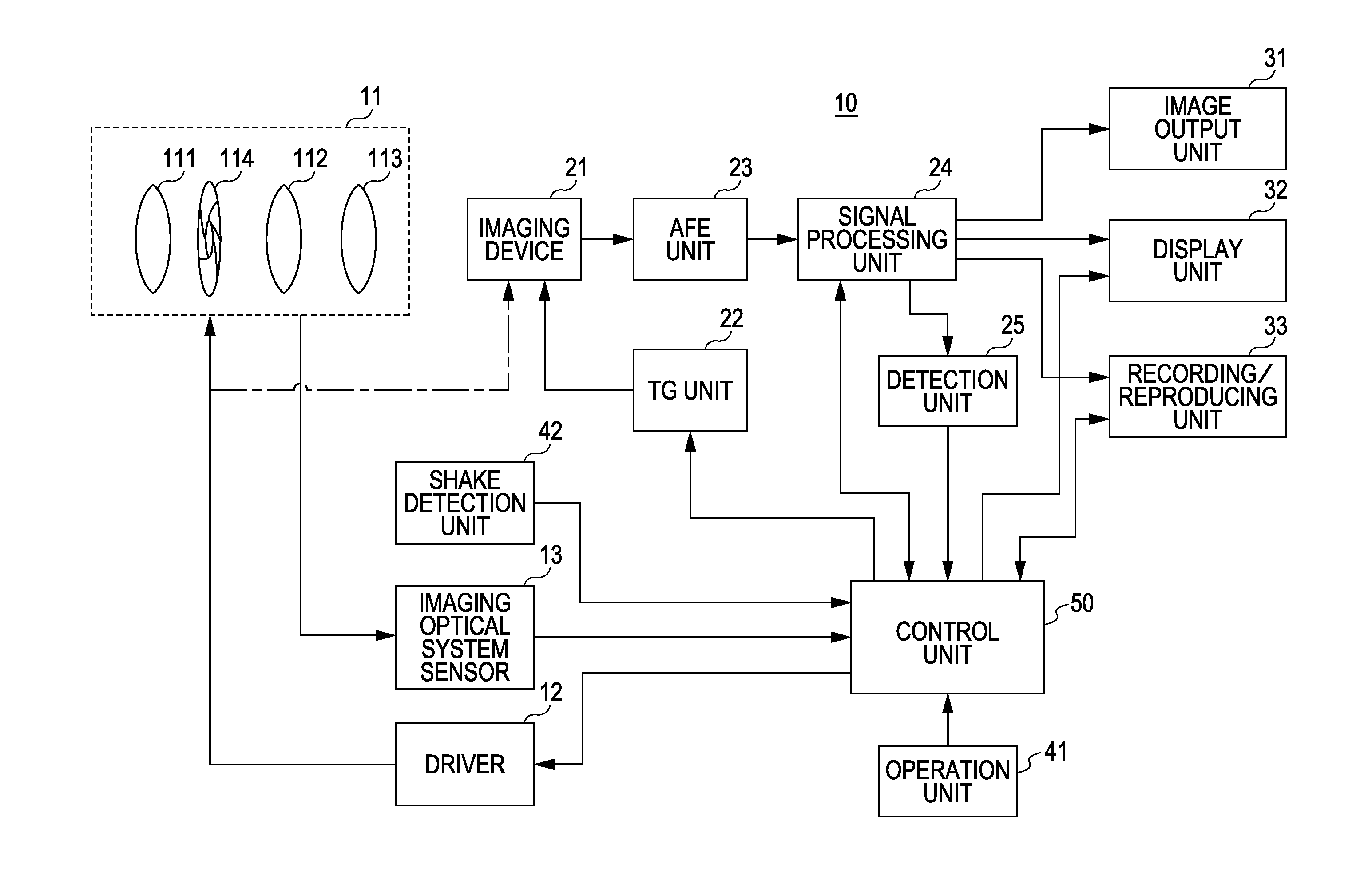
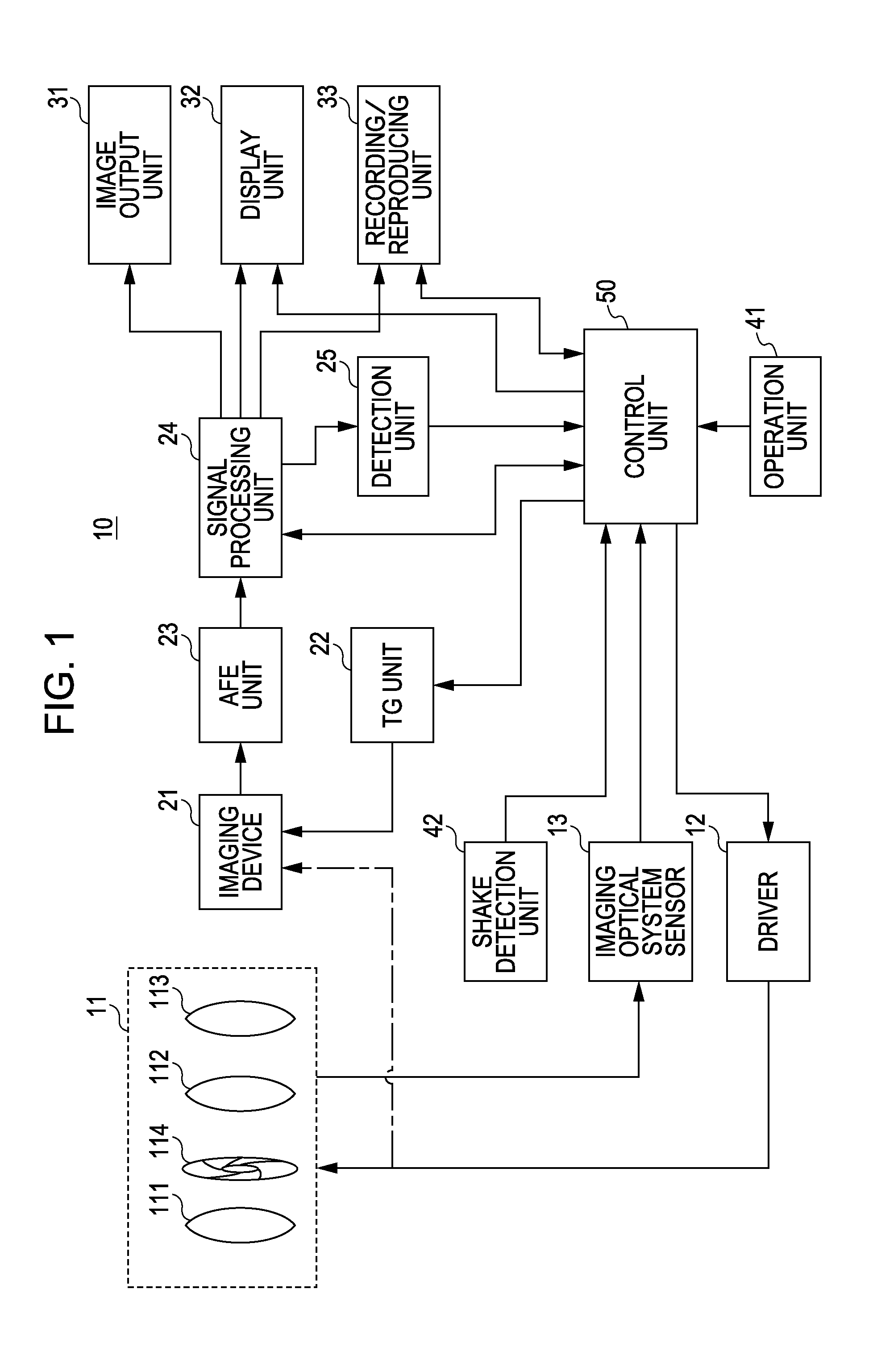
[0040]FIG. 1 is a block diagram showing the configuration of an imaging apparatus using a shake correction device according to an embodiment of the present invention. The imaging apparatus 10 includes an imaging optical system block 11, a driver 12, an imaging optical system sensor 13, an imaging d...


PUM


Abstract

A shake correction device includes a shake detection unit detecting shake so as to generate a shake detection signal, a driving unit displacing a relative positional relationship between a lens unit and an imaging device with respect to an optical axis so as to displace the position on the imaging surface of an optical image formed on an imaging surface of the imaging device, a displacement detection unit detecting a displacement state of the correction lens unit or the imaging device, a filter processing unit performing a filter process of the shake detection signal, and a correction control unit displacing the relative positional relationship between the lens unit and the imaging device according to the filter-processed shake detection signal so as to correct the shake of the optical image on the imaging surface generated by the shake detected by the shake detection unit.

Description

CROSS-REFERENCE TO RELATED APPLICATIONS[0001]This application is a continuation, of U.S. application Ser. No. 12 / 592,025, filed on Nov. 18, 2009, which claims priority from Japanese Patent Application No. JP 2008-315429 filed in the Japanese Patent Office on Dec. 11, 2008, the disclosures of which are incorporated herein by reference.BACKGROUND OF THE INVENTION[0002]1. Field of the Invention[0003]The present invention relates to a shake correction device, a shake correction method and an imaging apparatus and, more particularly, to performing of suitable shake correction using a correction area effectively.[0004]2. Description of the Related Art[0005]In the related art, in a shake correction mechanism of an imaging apparatus, shake is corrected by displacing a correction optical system, for example, a correction lens, without moving the position of an optical image on an imaging surface by shake of the device.[0006]In such a shake correction mechanism, an angle of an optical axis wh...

Claims


Application Information

Patent Timeline
Patent Type & Authority Applications(United States)
IPC IPC(8): H04N5/228
CPCH04N5/23248H04N23/68
Inventor TANAKA, KAZATO
Owner SONY CORP
Why Eureka
Try Eureka