Personal safety system and process for the operation of a personal safety system

a personal safety and system technology, applied in the field of personal safety systems, can solve the problem that the use of proof air conditioning systems is permissible, and achieve the effects of preventing a freezing up of heat exchangers, and increasing availability and operating safety

Active Publication Date: 2014-04-10
DRAGER SAFETY
View PDF11 Cites 3 Cited by
  • Summary
  • Abstract
  • Description
  • Claims
  • Application Information

AI Technical Summary

Benefits of technology

[0009]The advantage of the present invention lies in the fact that with the at least one first pressure reducer and the at least one second pressure reducer, the drop in pressure of the at first liquid carbon dioxide takes place in at least two separate steps, for example, from 200 bar as the pressure, under which the carbon dioxide is in the steel cylinders provided for the storage thereof, to at first 10 bar in the feed line to the heat exchanger and finally to 2 bar to 6 bar in connection with the output of the heat exchanger. By means of the at least two-step drop in pressure of the carbon dioxide, an otherwise freezing solid of the pipelines, in which the carbon dioxide flows, which may have to be dealt with, is prevented. This increases the availability and operating safety of the refuge chamber functioning as a personal safety system. Another advantage lies in the fact that in connection with the second pressure reducer such a pressure is reached, which makes possible the problem-free connection of other units, such as, for example, a pneumatic motor, without there being a risk that such a unit freezes solid and thus malfunctions or is even damaged and thus is not or at least not immediately again available for work even after thawing. This also increases the availability and operating safety of the refuge chamber because the availability of a pneumatic motor, which is usually guaranteed in this manner, results in a correspondingly guaranteed availability of a pneumatic blower with such a pneumatic motor and the pneumatic blower in turn is active for receiving a favorable air distribution and thus an efficient, comprehensive cooling, but is active for the continuous supply of ambient air to the heat exchanger as well, whereby the latter likewise helps prevent a freezing up of the heat exchanger or to at least markedly lower a risk in this respect.
[0010]In a special, optionally also alternative embodiment of the personal safety system, a heat exchanger is provided with a plurality of alternatingly or cyclically usable cooling coils. Two or more cooling coils are then alternatingly or cyclically usable and, for example, with two cooling coils, one of the two coils is used for cooling the ambient air in the refuge chamber, while the other cooling coil can thaw. This guarantees a high availability of the CO2 cooling system. In addition, in a heat exchanger with two or more cooling coils, one of the cooling coils functions as a primary cooling coil and the second and any other cooling coil functions as a redundant cooling coil, over to which it is possible to switch in case of a failure of the primary cooling coil. Consequently, the CO2 cooling system is fail-safe, whereby the fail-safeness increases further in case of more than two cooling coils and, in addition, the alternating / cyclical usability of the individual cooling coils is still retained.
[0011]The embodiment of the personal safety system with a heat exchanger with at least two cooling coils is considered as an alternative or in addition to an embodiment of the personal safety system with two pressure reducers, such that the embodiment with a heat exchanger with at least two cooling coils optionally also achieves independent inventive quality.
[0012]In a further embodiment of the personal safety system, a pneumatic blower driven from the CO2 reservoir in connection with the heat exchanger is provided. The pneumatic blower comprises a pneumatic motor driven by the CO2 stream and a fan driven by the pneumatic motor. The pneumatic blower can thus run without an electric line and is therefore especially suitable for use in potentially explosive areas like the personal safety system described here. With regard to the CO2 stream, the pneumatic blower is arranged in connection with the heat exchanger, such that with the fan driven by the pneumatic motor in the area of the heat exchanger, an air stream is generated that discharges the cold forming at the heat exchanger, by ambient air being continuously fed to the heat exchanger. This brings about, on the one hand, a good mixing of ambient air and thus the intentional cooling of the interior space of the refuge chamber and prevents, on the other hand, a freezing up of the heat exchanger because of the supply of warmer ambient air to the heat exchanger.
[0013]The above-mentioned object is also accomplished with a process for the operation of a personal safety system as described here and below. For this, provisions are made in the operating process that a pressure pending in a main pipe arising from a pressure, with which the carbon dioxide is fed, is lowered with the at least one first pressure reducer to an operating pressure for the heat exchanger and that a prevailing pressure in connection with the heat exchanger is lowered further with the at least one second pressure reducer before the carbon dioxide is fed to the pneumatic blower.
[0014]A further or even alternative embodiment of a process for the operation of a personal safety system as described here and below is characterized in that a plurality of cooling coils comprised by the heat exchanger is alternatingly or cyclically switched over, such that a freezing up of a cooling coil is prevented by one of the at least two cooling coils being used for cooling, while the or any other cooling coil can thaw.

Problems solved by technology

However, only an operation of special, so-called explosion-proof air conditioning systems is permissible in potentially explosive areas.

Method used


Image

  • Personal safety system and process for the operation of a personal safety system
  • Personal safety system and process for the operation of a personal safety system
  • Personal safety system and process for the operation of a personal safety system

Examples


Embodiment Construction

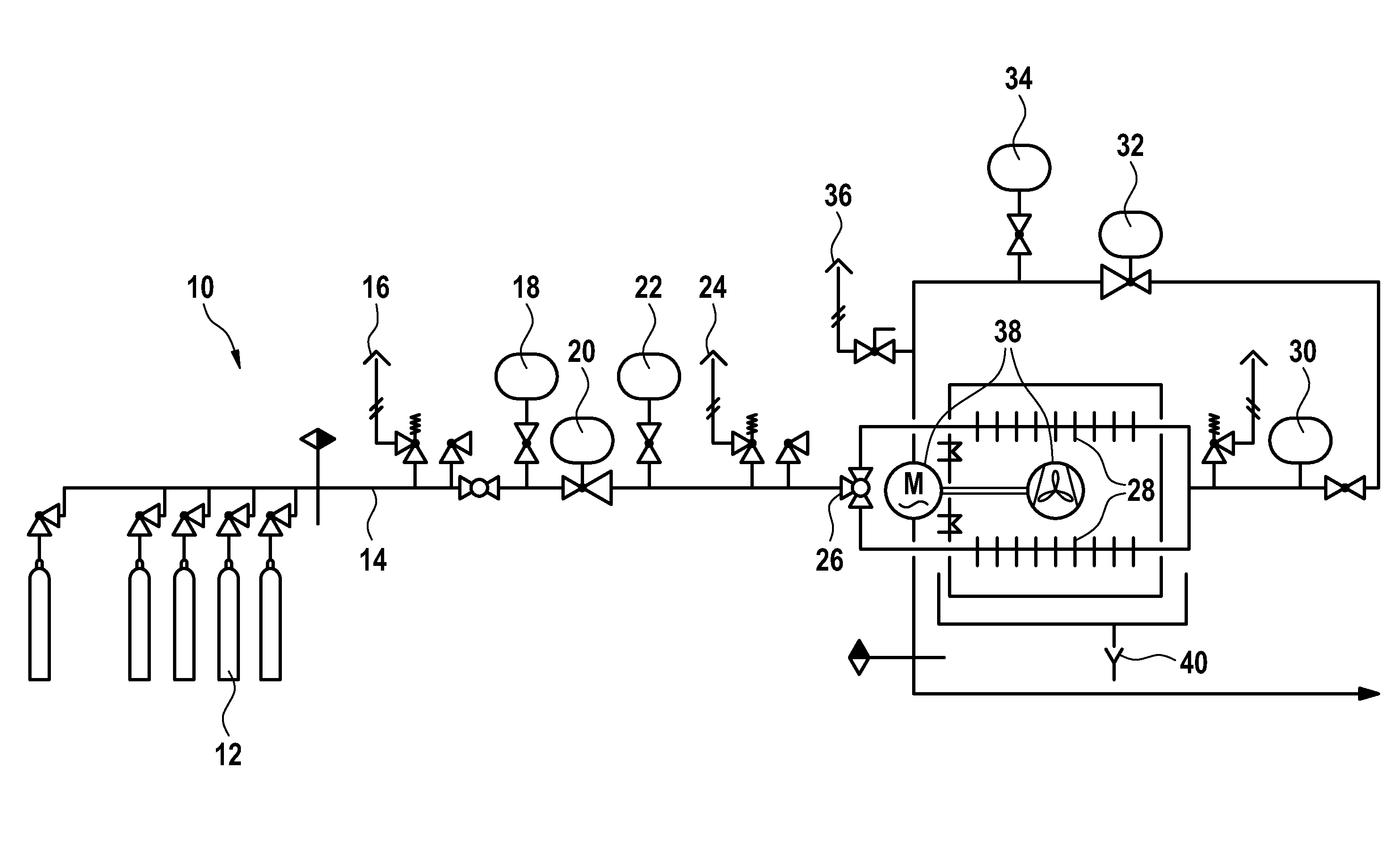
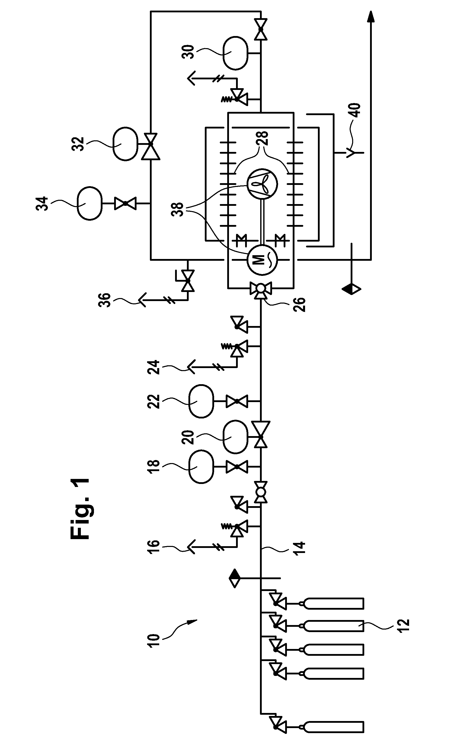
[0023]Referring to the drawings in particular, FIG. 1 shows in a schematically simplified schematic view a carbon dioxide cooling system also designated below in short as CO2 cooling system 10 for use in a personal safety system of the type mentioned in the introduction. This carbon dioxide cooling system 10 comprises, for example, one or more steel cylinders 12 each filled with liquid carbon dioxide as storage containers for liquid carbon dioxide and thus as CO2 reservoir. These steel cylinders 12 are connected via a main line 14 to a first safety valve 16, a first pressure indicator 18, a first pressure reducer 20, another pressure indicator 22, a second safety valve 24 and a three-way valve 26 at a heat exchanger 28, downstream of which are arranged a consumption indicator 30, another pressure reducer 32, a drain valve 34 and a third safety valve 36 on the output side.

[0024]A switching over between at least a first and a second cooling coil comprised by the heat exchanger 28 is p...


PUM


Abstract

A personal safety system in the form of a refuge chamber includes at least one main room and a cooling device provided for cooling the ambient air of the main room in the form of a CO2 cooling system (10). The CO2 cooling system (10) has a heat exchanger (28) and a first and a second pressure reducer (20, 32) upstream and downstream of heat exchanger (28), respectively. The heat exchanger (28) has a plurality of alternatingly or cyclically usable cooling coils. A process is provided for the operation of such a refuge chamber.

Description

CROSS REFERENCE TO RELATED APPLICATIONS[0001]This application claims the benefit of priority under 35 U.S.C. §119 of German Patent Application DE 10 2012 019 699.7 filed Oct. 6, 2012, the entire contents of which are incorporated herein by reference.FIELD OF THE INVENTION[0002]The present invention pertains to a personal safety system in the form or in the style of a so-called refuge chamber or a safety room, as it can be used for personal safety, for example, in mining, and especially in potentially explosive areas, i.e., for example, in coal mining. Furthermore, the present invention also pertains to a process for the operation of a personal safety system.BACKGROUND OF THE INVENTION[0003]For such refuge chambers / safety rooms, it is known that they need a cooling system if people stay in the interior thereof. An air conditioning system, or the like, is considered for the cooling system. However, only an operation of special, so-called explosion-proof air conditioning systems is per...

Claims


Application Information

Patent Timeline
Patent Type & Authority Applications(United States)
IPC IPC(8): F25D13/00
CPCF25D13/00E21F11/00F25D3/10
Inventor LUHR, MATTHIAS
Owner DRAGER SAFETY
Why Eureka
Try Eureka