Eureka AIR delivers breakthrough ideas for toughest innovation challenges, trusted by R&D personnel around the world.

Electronically compensated micro-speakers

a micro-speaker and electro-coefficient technology, applied in the field of electro-coefficient, can solve the problems of not addressing the method of significantly changing or improving the basic micro-speaker properties, johnson really teaches nothing that is useful in actually fabricating a useable system,

Inactive Publication Date: 2012-11-01
GOBELI GARTH WILLIAM +1
View PDF2 Cites 9 Cited by
  • Summary
  • Abstract
  • Description
  • Claims
  • Application Information

AI Technical Summary

Benefits of technology

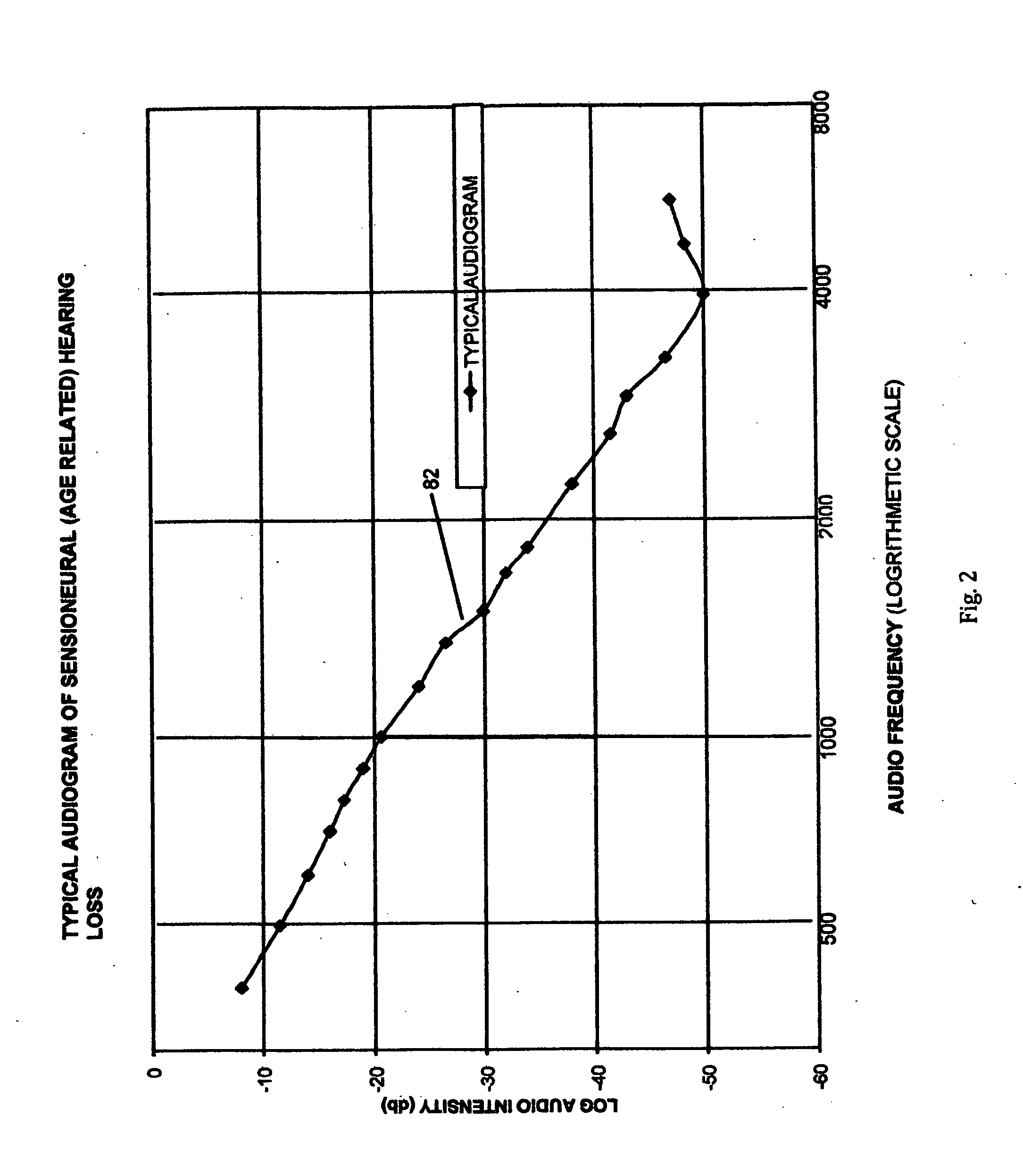
[0019]By judicious selection of resistance and capacitance values used in the various filter sections of this invention, it is possible to approximately correct such hearing deficiencies for the vast majority of such age-related hearing impaired individuals with a single compensation system. The truly attractive feature of such an approach is that it is “one-size-fits-all” in that a compensated earbud micro-speaker system fashioned in accordance with this invention only requires a user adjusted volume control and the user can compensate for hearing losses over a quite wide range of impairment. This fact results in a simple-to-manufacture device that offers impressive assistance to the hearing impaired at a cost that is a small fraction of the price of current hearing aids.
[0021]It is the object of this invention to provide a simple and direct means for changing / modifying the output audio spectrum of a variety of micro-speakers that are currently manufactured by a plethora of entities.
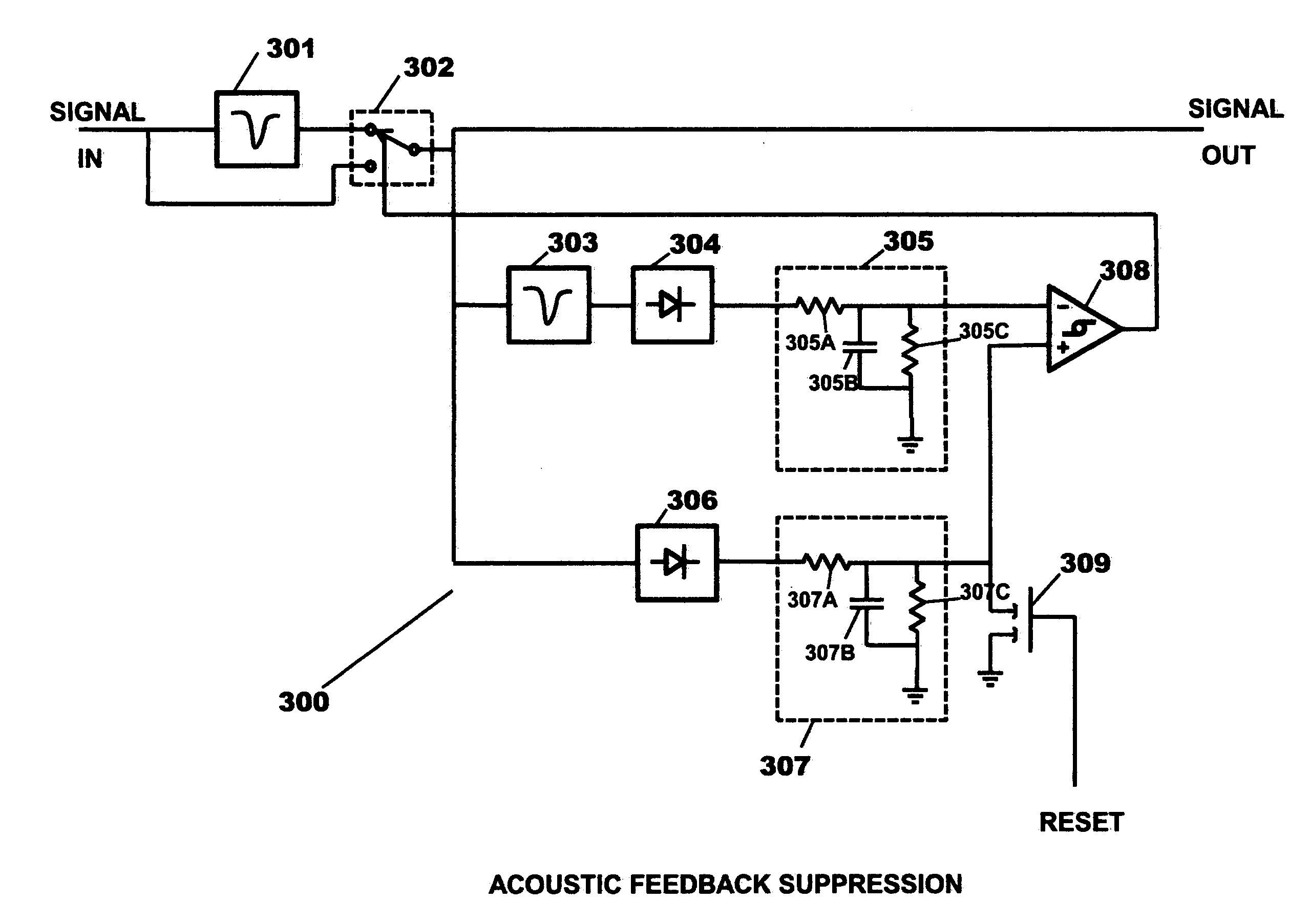
[0023]It is a further objective of this invention to provide a straightforward method of correcting the typical micro-speaker response by the careful and judicious use of a set of high-pass, low-pass filters, and high order filters.

Problems solved by technology

Those parameters describe the functionality of the micro-speaker itself but do not address methods of significantly changing or improving the basic micro-speaker properties.
Due to these significant differences noted above, one cannot justifiably apply analyses and corrective measures that are proposed for “generally known speakers” to an analysis and corrective measures for micro speakers.
In fact, Johnson really teaches nothing that is useful in actually fabricating a useable system.
This patent does not address changing the spectrum of a micro-speaker.

Method used


Image

  • Electronically compensated micro-speakers
  • Electronically compensated micro-speakers
  • Electronically compensated micro-speakers

Examples


Embodiment Construction

[0032]The definition of a micro speaker is related to both its size and its basic construction. The size is from 14 mm diameter to 9 mm diameter and smaller. Its construction puts the magnet into the shape of a slab, rather than a hollow cylinder of the “generally known speakers”. The vibrating element is a very thin membrane suspended above the magnet center rather than being cone shaped as in “generally known speakers”

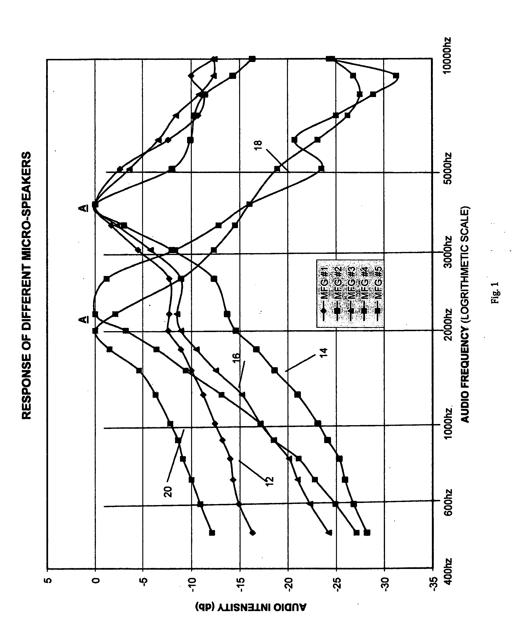
[0033]The experimentally measured output acoustic spectra of some commercially available earbud micro-speakers are illustrated in FIG. 1 for five different manufacturers (12, 14, 16, 18, and 20). Note that each speaker has a resonant peak region (A) in the audio intensity as a function of audio frequency. The location of each resonant peak region lies between 2000 Hz and 4000 Hz, with the smaller diameter earbud micro-speakers that have rare-earth magnets being at the higher frequencies. In all cases shown in FIG. 1, the response declines for frequencies both higher ...


PUM


Abstract

Electronics for altering the audio frequency response of a micro-speaker without modifying the micro-speaker itself are used to provide a selected frequency response of the micro-speaker. The micro-speaker has a resonant peak region, from which the response declines for both higher and lower frequencies. In one embodiment the electronics includes a first circuit for modifying the frequency response curve up to the resonant peak region, and a second circuit for modifying the frequency response curve for audio frequencies higher than this region. Each filter yields an integer multiple of 6 dB per octave slope. In the described embodiment, for approximately correcting presbyacusis (age related hearing loss), a set of high pass filters, low pass filters, and / or high order filters are connected to the micro-speaker to progressively attenuate the frequency response curve as the frequency decreases from 10000 Hz to 100 Hz.

Description

[0001]This application is a Continuation In Part of patent application Ser. No. 12 / 423,990 Filed Apr. 15, 2009BACKGROUND OF THE INVENTION[0002]This invention pertains to the electronic compensation of the existing micro-speakers contained in earphones or earbud headsets. The compensation is designed to modify the normal micro-speaker output as a function of acoustic frequency so as to: (1) produce a desired response that can compensate for the hearing deficiency of users, usually elderly, that suffer from presbycusus, or age-related hearing loss, which is characterized by a hearing loss that becomes more severe as the acoustic frequency moves to higher tones. Other chosen frequency characteristics can be similarly provided.[0003]A micro speaker is significantly different from “the generally known speaker” as shown in U.S. Pat. No. 6,553,126 by Han et. al (2003). He describes the generally known speaker in (col. 1, ln. 14-20). The “conventional micro speaker” is described in (col. 1,...

Claims


Application Information

Patent Timeline
Patent Type & Authority Applications(United States)
IPC IPC(8): H03G5/00H04B15/00
CPCH04R25/00H04R3/04
Inventor GOBELI, GARTH WILLIAMMILLS, STEPHEN
Owner GOBELI GARTH WILLIAM
Why Eureka
Eureka Blog
Learn More