
Rotating Electrical Plug Assembly for Volatile Material Dispenser

a technology of electrical plugs and volatile materials, which is applied in the direction of lighting and heating apparatus, heating types, coupling device connections, etc., can solve the problems of plug assembly parts to fatigue, undesirable rotation of the dispenser in this manner, and leakage of volatile materials

Inactive Publication Date: 2012-11-01
BELONGIA DAVID C
View PDF7 Cites 8 Cited by
  • Summary
  • Abstract
  • Description
  • Claims
  • Application Information

AI Technical Summary

Benefits of technology

[0042]The present invention provides a volatile material dispenser having a rotating electrical plug assembly. The plug assembly includes a cap integrally molded with a support block, which is adapted to support electrical wires. The wires are disposed within notches and held therein by a rib that extends outwardly from the cap. The connection point between the rib and the wires allows for strain to be dissipated as opposed to acting on ends of the wires.
[0043]Numerous modifications to the present invention will be apparent to those skilled in the art in view of the foregoing description. Accordingly, this description is to be construed as illustrative only and is presented for the purpose of enabling those skilled in the art to make and use the invention and to teach the best mode of carrying out same. The exclusive rights to all modifications which come within the scope of the appended claims are reserved.

Problems solved by technology

One of the disadvantages of many of the volatile material dispensers and refills therefore, such as the plug-in scented oil dispenser discussed above, is that the plug assembly and electrical prongs are oriented in such a way so as to be compatible with only a single orientation of the volatile material dispenser with respect to the electrical outlet.
Rotation of the dispenser in this manner is undesirable for numerous reasons including, at least, that the volatile material may leak from the dispenser and / or be removed from contact with the wick if the dispenser is disposed in a horizontal position.
However, a further problem is created by the continued rotation of the plug assembly of the present devices utilizing such an assembly.
Specifically, strain is created on various portions of the plug assembly during rotation, which causes the plug assembly parts to fatigue over time.
The fatigue may lead to loose wires in the plug assembly that could create unstable connection points between the plug assembly and the wires and render the volatile material dispenser inoperable.

Method used


Image

  • Rotating Electrical Plug Assembly for Volatile Material Dispenser
  • Rotating Electrical Plug Assembly for Volatile Material Dispenser
  • Rotating Electrical Plug Assembly for Volatile Material Dispenser

Examples


Embodiment Construction

[0026]The present invention is directed to an electrical plug assembly for a volatile material dispenser. While the present invention may be embodied in many different forms, several specific embodiments are discussed herein with the understanding that the present invention is to be considered only as an exemplification of the principles of the invention, and it is not intended to limit the invention to the embodiments illustrated.

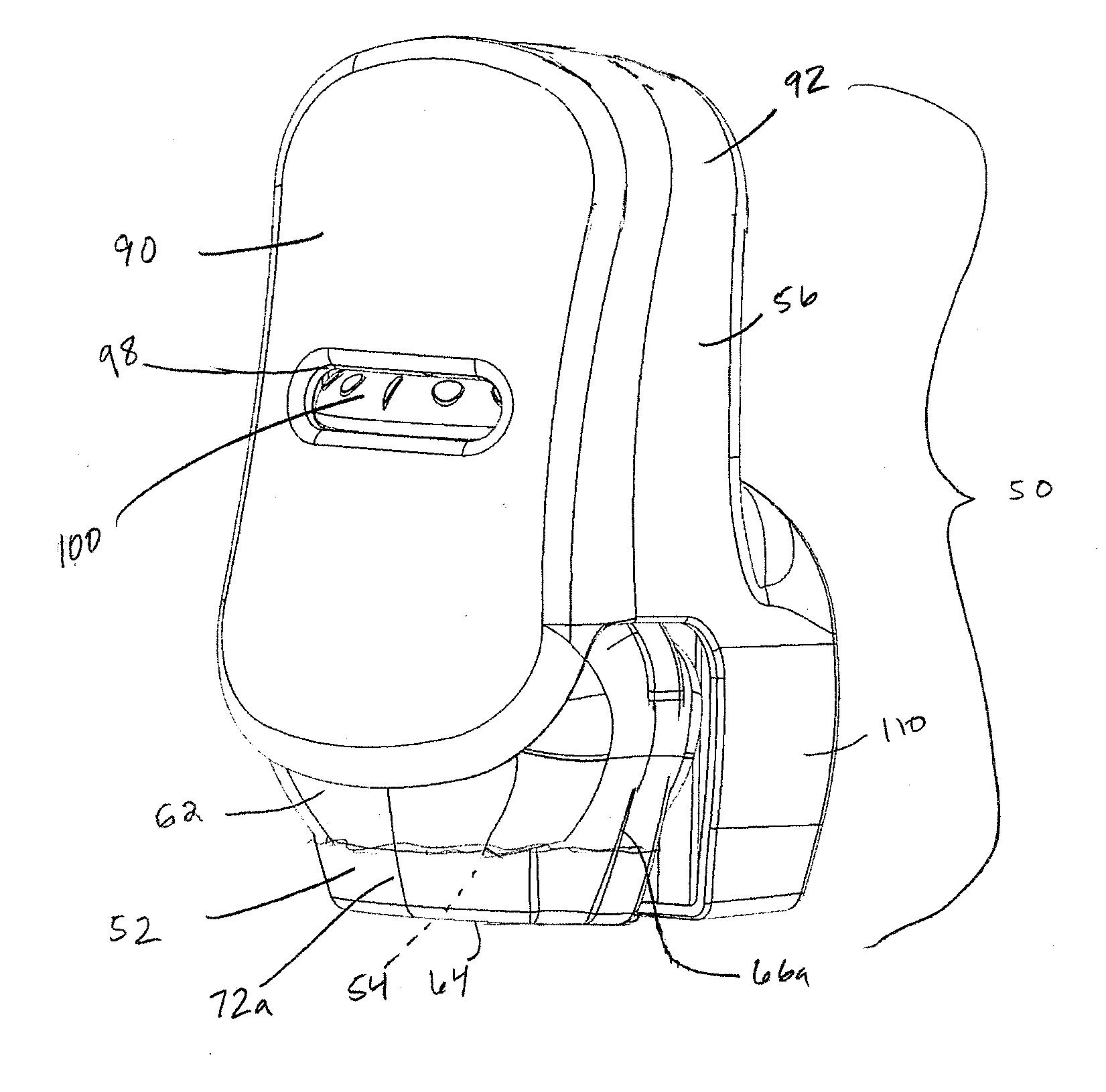
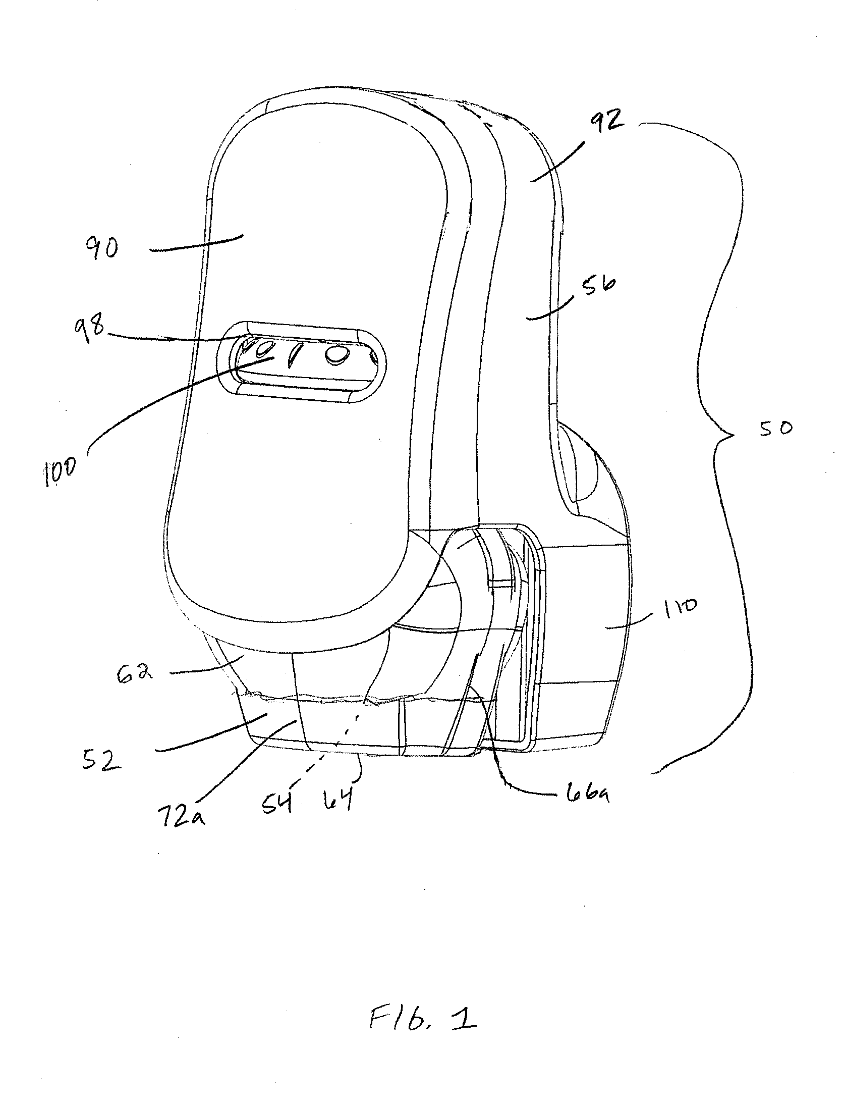
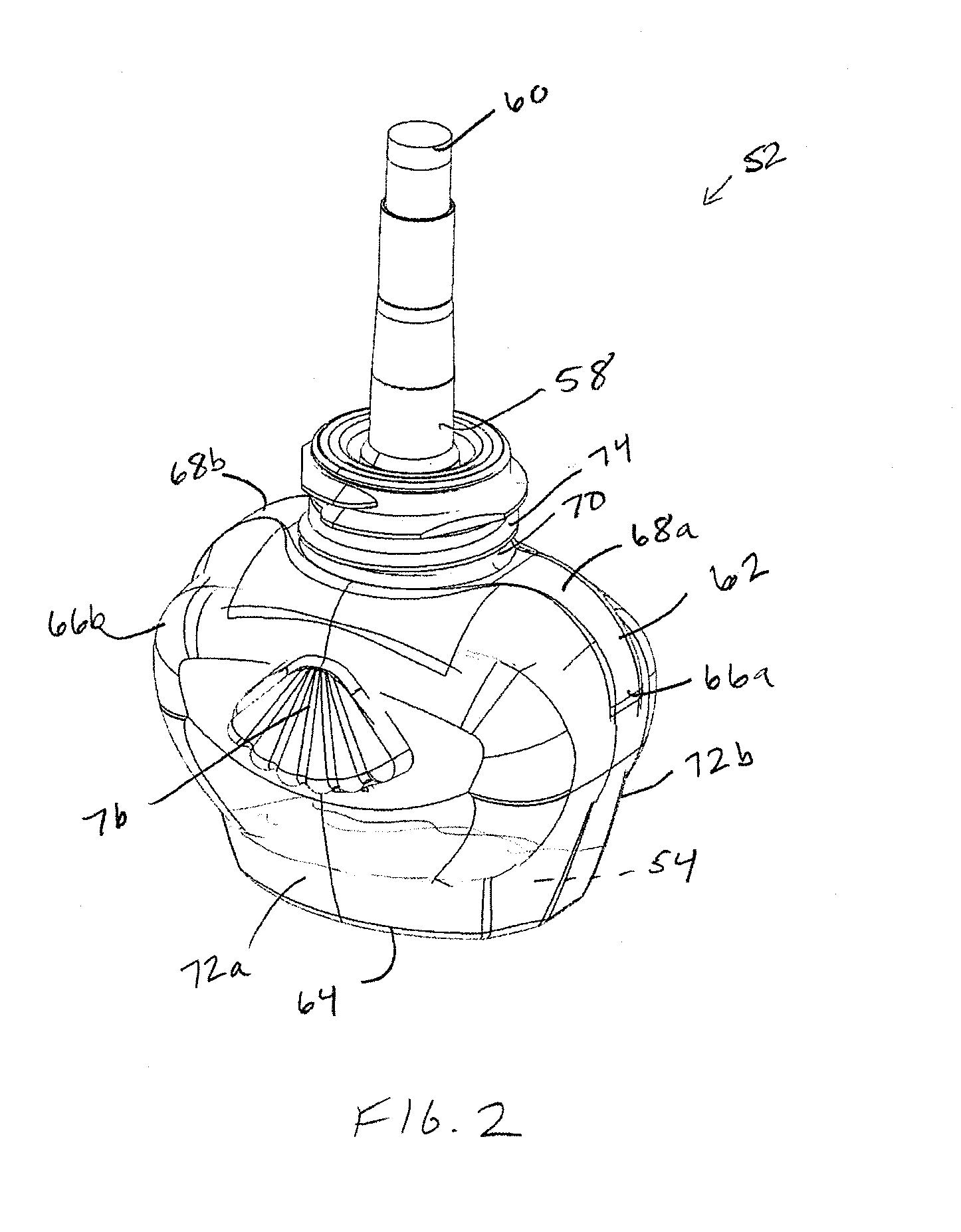
[0027]Referring to the drawings, FIG. 1 depicts a volatile material dispenser 50 having a container 52 with a volatile material 54 therein, which is adapted to be retained by a housing 56. As best seen in FIG. 2, the container 52 includes a retaining mechanism 58 to hold a wick 60 within the container 52. The container 52 includes a body 62 with the volatile material 54 disposed therein. The body 62 includes a base portion 64 and first and second opposing sidewalls 66a, 66b that extend upwardly and outwardly prior to curving inwardly toward first and secon...


PUM


Abstract

A support block for a rotatable plug assembly includes a base and electrical plug pins extending outwardly therefrom. A medial wall extends from the base. A cap is hingedly attached to the medial wall and is moveable between open and closed positions. A sidewall extends from the medial wall and has at least one notch disposed therein. At least one electrical wire is connected to the support block and extends through the at least one notch. The cap fixedly retains the at least one electrical wire within the at least one notch when in the closed position.

Description

CROSS REFERENCE TO RELATED APPLICATIONS[0001]Not applicable.REFERENCE REGARDING FEDERALLY SPONSORED RESEARCH OR DEVELOPMENT[0002]Not applicableSEQUENTIAL LISTING[0003]Not applicableBACKGROUND OF THE INVENTION[0004]1. Field of the Invention[0005]The present invention relates generally to a rotating electrical plug assembly and, more particularly, to a rotating electrical plug assembly for use in a volatile material dispenser.[0006]2. Description of the Background of the Invention[0007]Various volatile material dispensers are known in the prior art and generally include a housing with a refill inserted therein. The refill generally includes a container for holding a volatile material therein. In some dispensers, the volatile material is passively emitted therefrom. In other dispensers, a diffusion element is utilized to facilitate the dispensing of the volatile material. Examples of diffusion elements include heaters, piezoelectric elements, fans, aerosol actuators, and the like. Rega...

Claims


Application Information

Patent Timeline
IPC IPC(8): A61M16/00
CPCH01R13/5829H01R24/68A61L9/037H01R2103/00H01R35/04H01R13/58A61L9/03
Inventor BELONGIA, DAVID C.
Owner BELONGIA DAVID C
Learn More