Retractable speed bump

a speed bump and retraction technology, applied in roads, roads, construction, etc., can solve the problem of not having enough time for the bump to fall o

Inactive Publication Date: 2012-11-08
HUA CHEYENNE
View PDF4 Cites 21 Cited by
  • Summary
  • Abstract
  • Description
  • Claims
  • Application Information

AI Technical Summary

Benefits of technology

[0009]A retractable speed bump mounted in a street, road or roadway for controlling the speed of vehicles, which includes three main components: enabling bar, bump, and link mechanism. The enabling bar lies horizontally across the road surface; it i...

Problems solved by technology

If the vehicle exceeds the speed limit, the bump does not have sufficient time to fall a...

Method used


Image

  • Retractable speed bump
  • Retractable speed bump
  • Retractable speed bump

Examples


Embodiment Construction

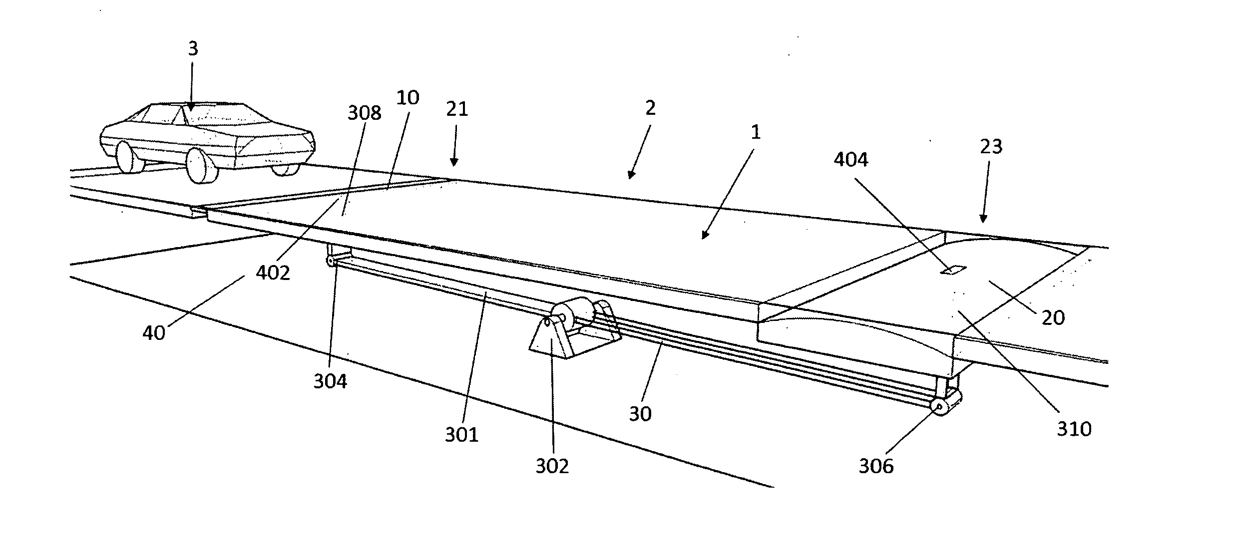
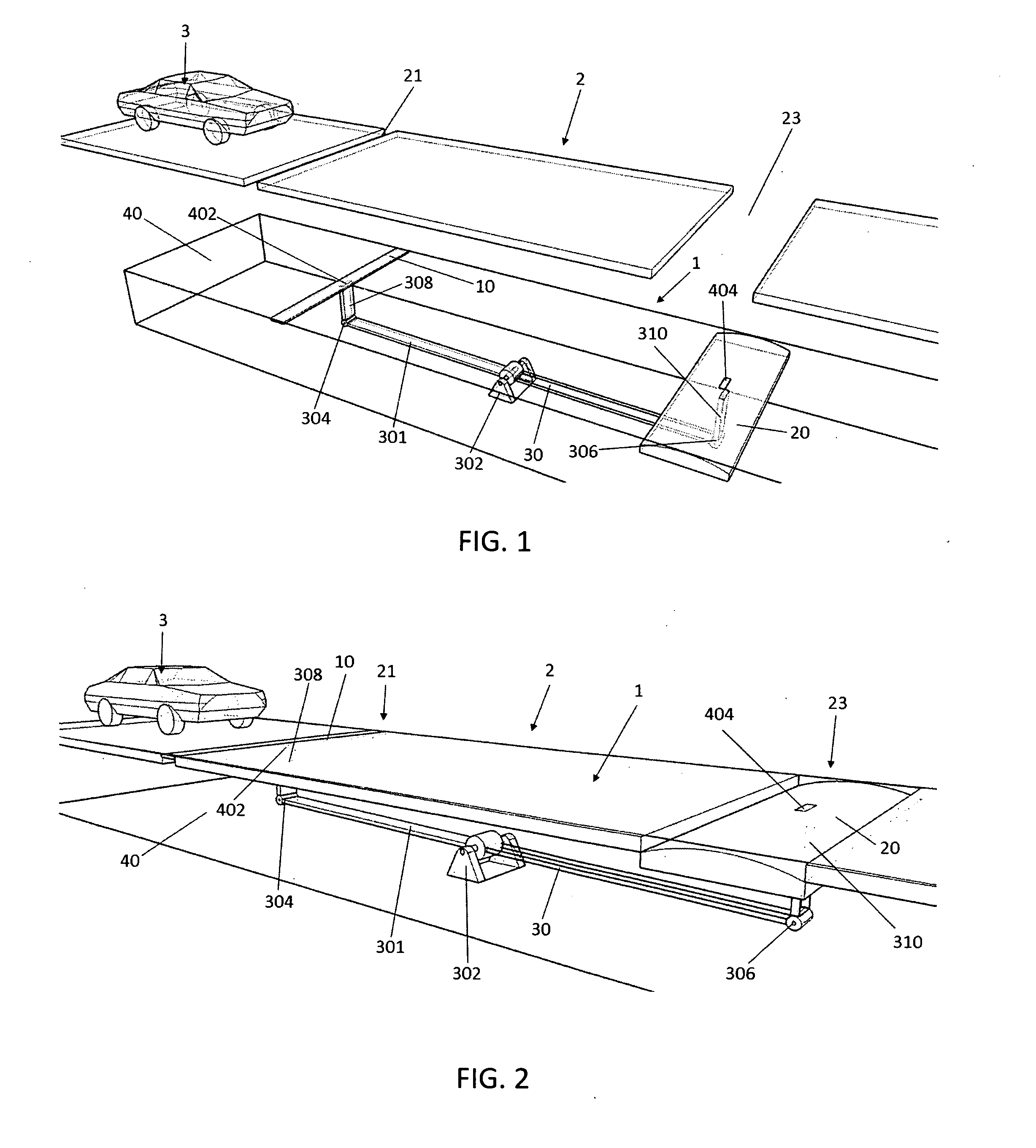
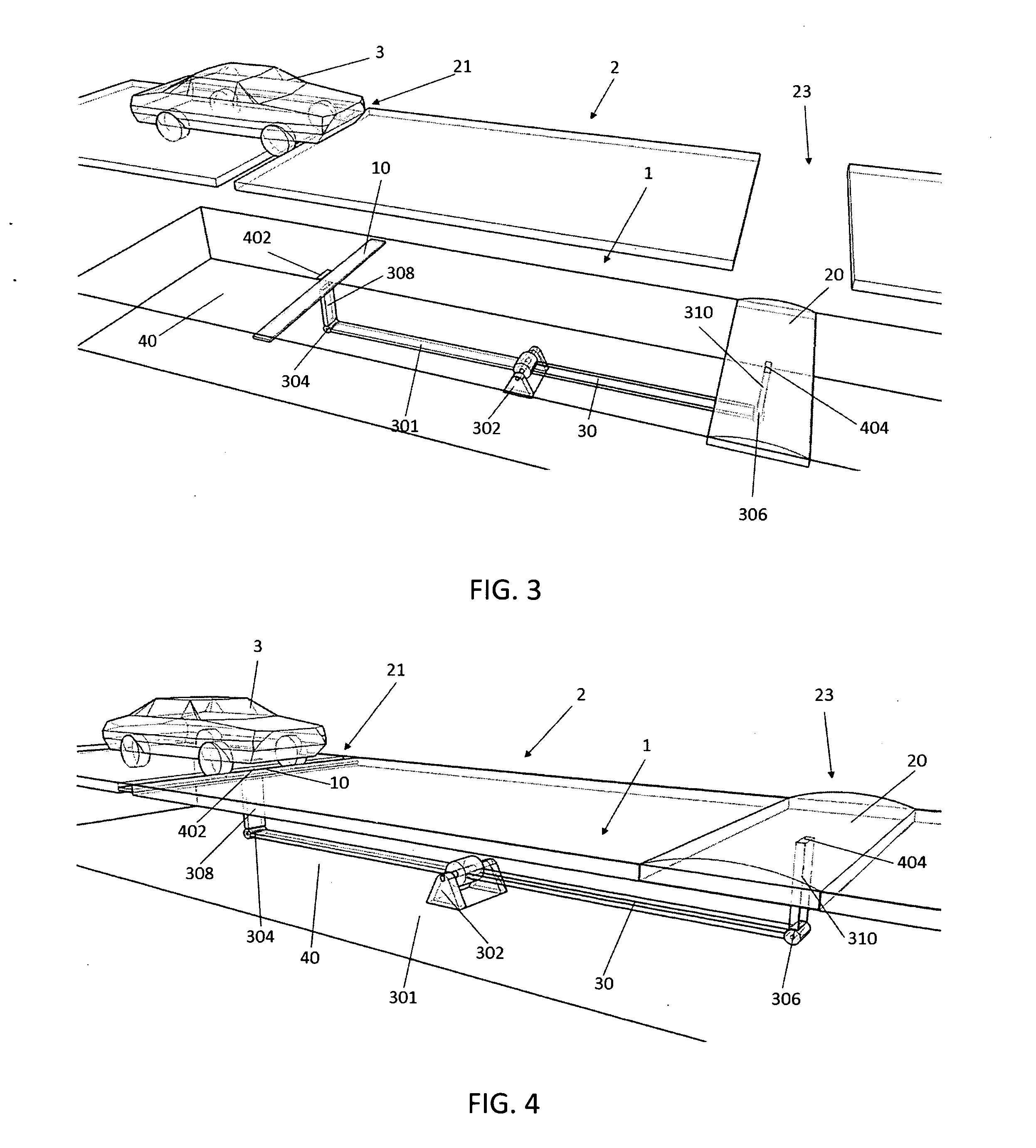
[0026]Referring to FIG. 1 to FIG. 4, there are disclosed an embodiment of the speed bump device according to the present invention. The embodiment is designed based on simple mechanics—class 1 lever mechanism. The speed bump device 1 comprises three major components: an enabling bar 10, a speed bump 20, and a link mechanism which is a class 1 lever 30 in this embodiment. The class 1 lever 30 includes a lever arm 301 having a first end 304 under the enabling bar 10, and a second end 306 under the speed bump 20, and a fulcrum 302 at the middle of the lever arm 301. The enabling bar 10 is connected to the first end 304 by means of column 308 and the speed bump is connected to the second end 306 by means of column 310. The lever 1 is installed inside a strong, rigid and corrosion resistant rectangular shaped encasement 40 which has two openings on the top next to the road surface 2. The first opening 402 allows the column 308 to protrude out and retracts back into the encasement 40 so t...


PUM


Abstract

A retractable speed bump mounted in a street, road or roadway for controlling the speed of vehicles, which includes three main components: enabling bar, bump, and a link mechanism. The speed bump rests in the grooves on the road surface when it is not in operation. When a vehicle moves over the enabling bar, the tire runs on top of the enabling bar, pushing the enabling bar downward. This downward force triggers the link mechanism and pushes the bump up out of the grooves on the road surface. In one embodiment according to the present invention, the link mechanism is a class 1 lever.

Description

BACKGROUND OF THE INVENTION[0001]1. Field of the Invention[0002]The present invention generally relates to vehicle speed control means and more particularly to an improved vehicle speed bump device.[0003]2. Description of Related Art[0004]Generally, speed bumps are frequently embedded in roadways or placed on top of the roadway to regulate the speed of vehicles crossing over them. The speed bumps are generally low enough for vehicles to safely cross yet high enough to force a vehicle to slow down while crossing otherwise causing a substantial jolt to the vehicles. However, even when the speed of the vehicle has been reduced, a substantial jar is often imparted to the vehicle. In some cases, the speed bump can strike the frame of the vehicle; it happens especially to the sports car or sedan because they are low to the ground. Because of this indiscriminate effect on vehicles traveling over speed bumps, attempts have been made to produce retractable speed bumps.[0005]U.S. Pat. No. 4,3...

Claims


Application Information

Patent Timeline
IPC IPC(8): E01F11/00
CPCE01F9/047E01F9/529
Inventor HUA, CHEYENNE
Owner HUA CHEYENNE
Why Eureka
Try Eureka