Method and System for Vehicular Traffic Management

a technology for vehicular traffic and management methods, applied in traffic signals, roads, road signs, etc., can solve problems such as not allowing regular passenger vehicles to pass through, and achieve the effect of increasing visibility

Inactive Publication Date: 2007-10-11
MOSCOVITCH JERRY
View PDF9 Cites 16 Cited by
  • Summary
  • Abstract
  • Description
  • Claims
  • Application Information

AI Technical Summary

Benefits of technology

[0007]The speed bump system can be pre-fabricated or constructed on site. Reflectors can be disposed between the gaps to increase visibility for emergency vehicles at night.

Problems solved by technology

In one embodiment that can be implemented when the tire configuration (e.g., width of tires, number of tires, distance between front tires, distance between rear tires) of the emergency vehicle is substantially different from that of a regular passenger vehicle, the speed bump system is designed to allow an emergency vehicle to pass through the gaps, but to not allow the regular passenger vehicle to pass through the gaps.

Method used


Image

  • Method and System for Vehicular Traffic Management
  • Method and System for Vehicular Traffic Management
  • Method and System for Vehicular Traffic Management

Examples


Embodiment Construction

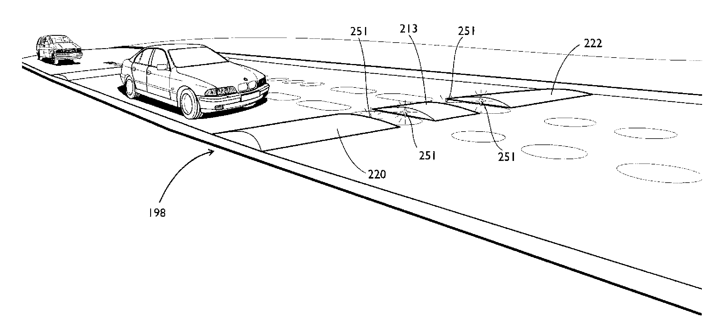
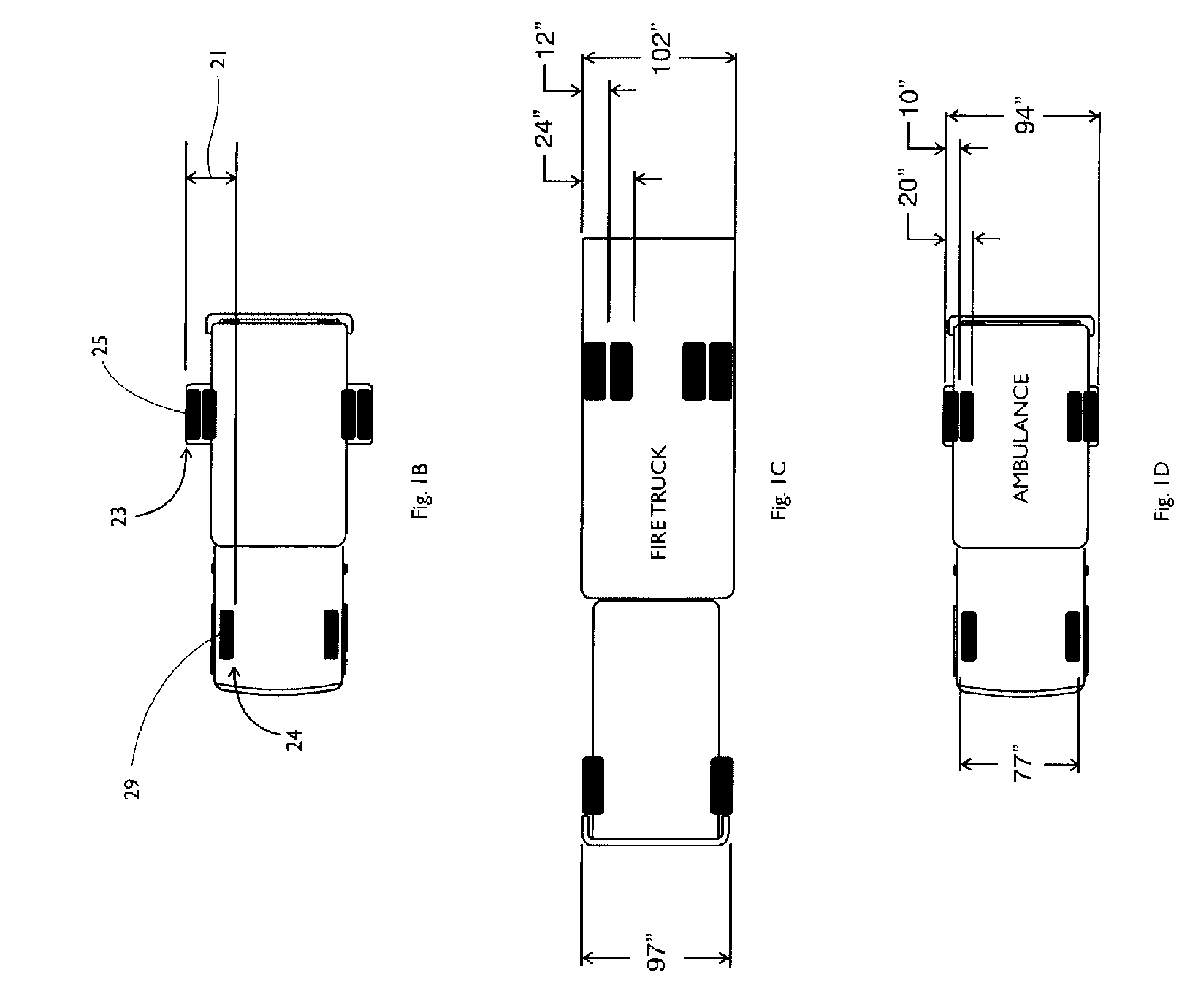
[0023]A speed bump system is described below that provides the traditional benefits of speed bumps, viz., reducing speeds of cars, while not impeding the speed of emergency vehicles.

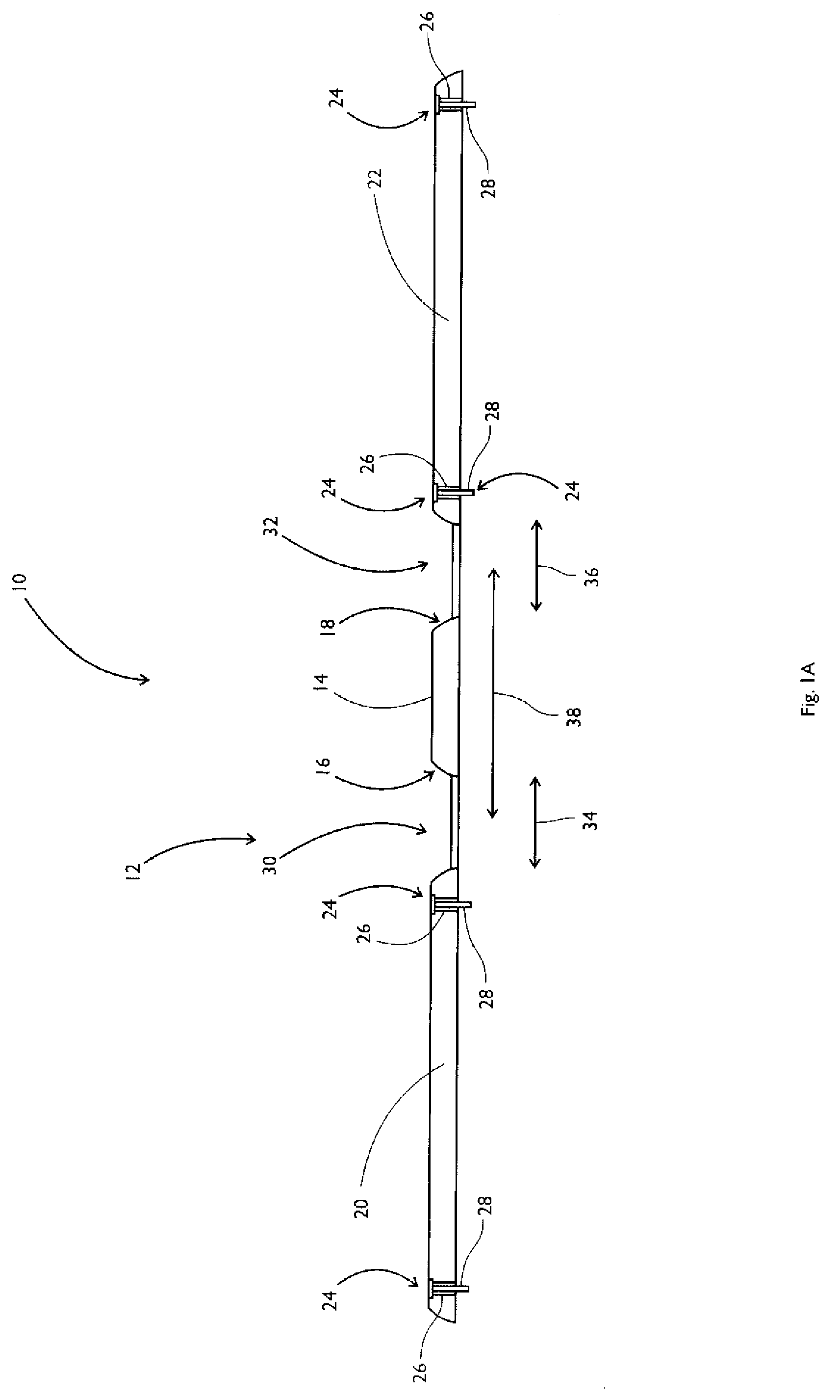
[0024]FIG. 1A shows a cross-sectional view of a speed bump system 10 for a roadway that encourages a driver of a vehicle to slow down. The system 10 is designed, however, to not impede an emergency vehicle. An emergency vehicle can include an ambulance, a fire truck and / or a police car, for example.

[0025]The speed bump system 10 includes an elongate structure 12 having a raised middle portion 14 with two ends 16 and 18. The elongate structure 12 also has a first raised outer portion 20 that is proximal to the one end 16 of the raised middle portion 14, and a second raised outer portion 22 that is proximal to the other end 18 of the raised middle portion 14. The speed bump system 10 also includes affixing means 24 that can include holes 26 and screws 28 threaded therethrough and screwed to the roadway. An...


PUM


Abstract

A speed bump system and method for a roadway that encourages a driver of a passenger vehicle to slow down and that does not substantially impede an emergency vehicle are described herein. The system includes a structure for disposing across the roadway to encourage the driver of a passenger vehicle to slow down before driving over the structure. In one embodiment, the structure has a raised middle portion, a first raised outer portion proximal to one end of the raised middle portion, and a second raised outer portion proximal to the other end of the raised middle portion. The three raised portions are traversable by the passenger vehicle. The structure further includes a first gap between the first raised outer portion and the raised middle portion, and a second gap between the second raised outer portion and the raised middle portion. The width of the first gap, the width of the second gap and the distance between the first and second gaps allow the emergency vehicle to pass through the first and second gaps.

Description

FIELD OF THE INVENTION[0001]The invention relates to vehicular traffic management, and more particularly to managing such traffic using speed bumps.BACKGROUND OF THE INVENTION[0002]Speed bumps are a widespread means for controlling traffic. They are often used in locations where the potential for collisions is greater than normal, such as in construction zones, toll ways, entrance and exit ramps, school zones and residential areas.[0003]A typical speed bump is a permanent structure integrated with a road surface, such as an asphalt, concrete, or steel structure whose shape resembles that of a cylinder sliced longitudinally. The speed bump is placed across a road to encourage drivers of vehicles to slow down when passing thereon lest they suffer a large jolt.[0004]Despite their effectiveness, there is at least one drawback associated with conventional speed bumps. Emergency vehicles, such as ambulances, police cars and fire trucks, are forced to slow down when traversing a speed bump...

Claims


Application Information

Patent Timeline
Patent Type & Authority Applications(United States)
IPC IPC(8): E01F11/00E01F9/529
CPCE01F9/047E01F9/529
Inventor MOSCOVITCH, JERRY
Owner MOSCOVITCH JERRY
Why Eureka
Try Eureka