Rotary cutting tool having a cutting edge formed of veined pcd

a cutting edge and rotary cutting technology, which is applied in the field of rotary cutting tools, can solve the problems of high power consumption, undesired heating of the cutting tool, and chips that adhere to the tooth face, and achieve the effect of facilitating minimal pcd removal

Inactive Publication Date: 2012-11-08
KENNAMETAL INC
View PDF40 Cites 28 Cited by
  • Summary
  • Abstract
  • Description
  • Claims
  • Application Information

AI Technical Summary

Benefits of technology

The technical effect of this patent is to modify the shape of teeth on PCD rotary cutters to improve their performance. This modification can be achieved by creating a special blank from which excess material can be easily removed during manufacturing.

Problems solved by technology

The technical problem addressed in this patent is to improve the energy and chip disposal properties of PCD cutting tools, particularly for machining materials that are hard to cut such as composite plastics reinforced with fibers of glass, carbon, boron or Kevlar. The solution needs to be applicable to PCD cutting tools and not require excessive removal of PCD material.

Method used


Image

  • Rotary cutting tool having a cutting edge formed of veined pcd
  • Rotary cutting tool having a cutting edge formed of veined pcd
  • Rotary cutting tool having a cutting edge formed of veined pcd

Examples


first embodiment

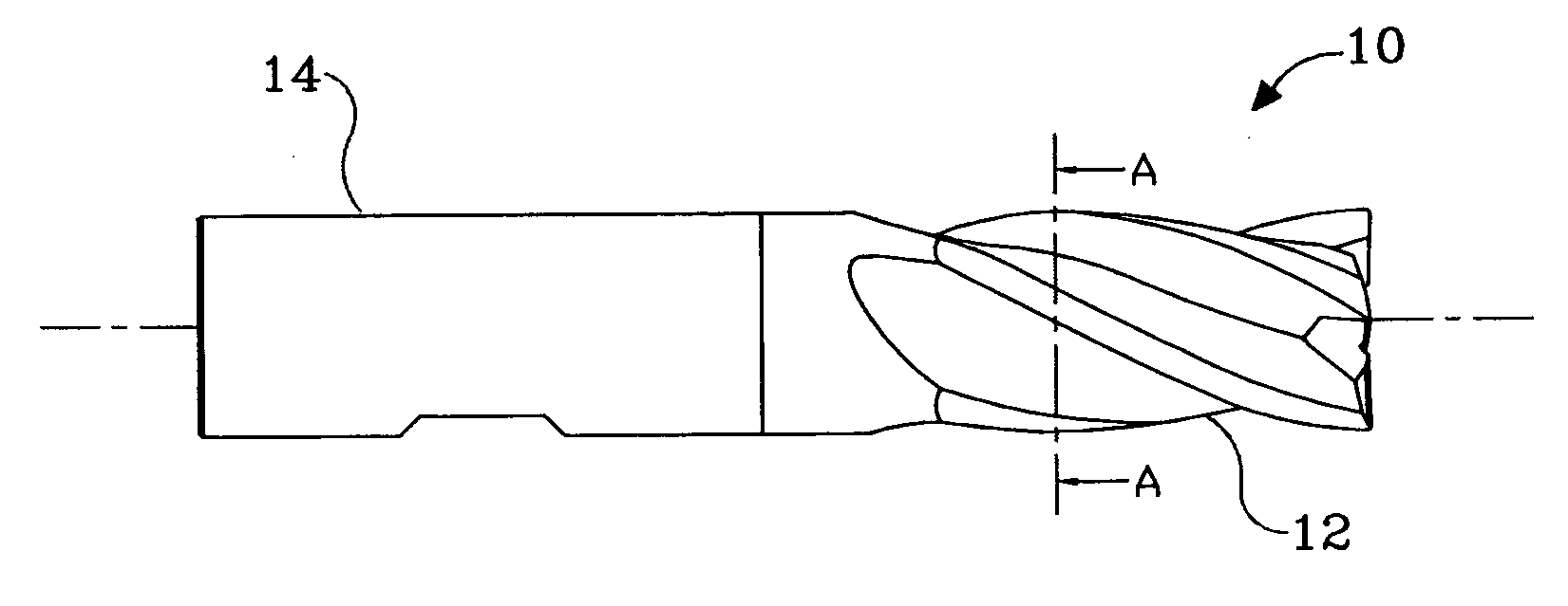
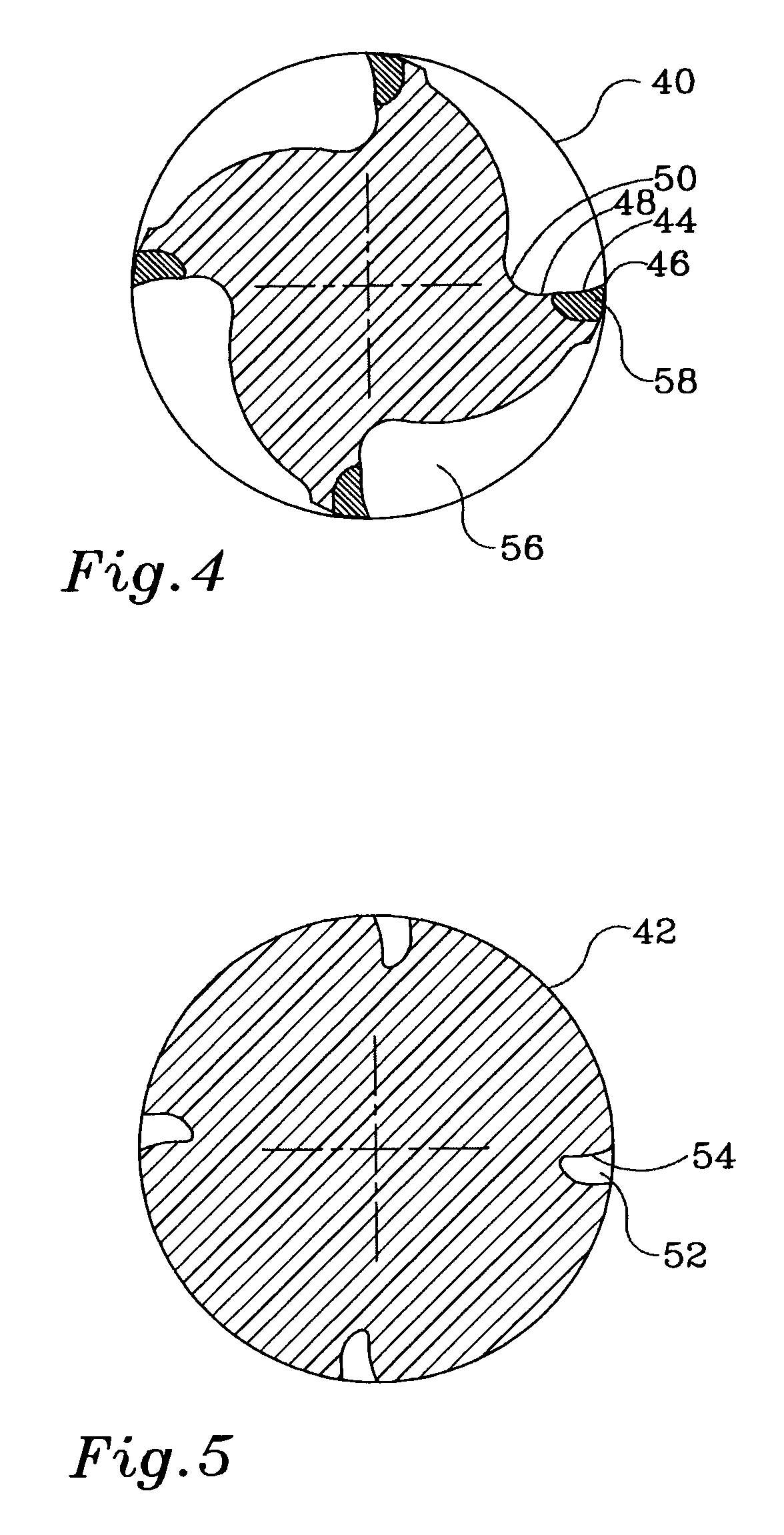
[0030]Referring to FIGS. 4 and 5, there are shown a four flute PCD rotary cutter 40 and corresponding blank 42 made in accordance with the present invention. The tooth face, as viewed in a cross-section perpendicular to the cutter axis, is divided into two sections: a first concave section 44 (constituting a first curved surface) proximate the cutting edge 46, and a second concave section 48 (constituting a second curved surface) proximate the tooth root 50 and abutting the first section 44. The TC blank 42 is provided with grooves 52 formed with a leading face 54 corresponding to the shape of the first concave section 44 of the cutter 40. In some embodiments, the first concave section 44 is smaller than the second concave section 48.

[0031]Subsequent to compacting and sintering of PCD veins in grooves 52, the flutes 56 are formed by a standard grinding operation. The first concave section 44 of the PCD veins is exposed with close tolerance to final shape, and minimal EDM operation i...

second embodiment

[0033]With reference to FIGS. 6 and 7, there is shown a four flute PCD rotary cutter 60 and corresponding TC blank 62 made in accordance with the present invention. The tooth face, as viewed in cross-section perpendicular to the cutter axis, is divided into two sections, a first convex section 64 (constituting a first curved surface) proximate the cutting edge 66, and a second concave section 68 (constituting a second curved surface) proximate the tooth root 70 and abutting the first section 44. The blank 62 is provided with grooves 72 formed with leading face 74 corresponding to the final convex shape of the first convex section 64 of the cutter 60. In some embodiments, the first convex section 64 is smaller than the second concave section 68.

[0034]Subsequent to compacting and sintering of PCD veins in grooves 72, the flutes 76 are formed by a standard grinding operation. The first convex section 64 of the PCD veins is exposed with close tolerance to final shape, and minimal EDM op...


PUM

PropertyMeasurementUnit
Shapeaaaaaaaaaa
Widthaaaaaaaaaa
Perimeteraaaaaaaaaa

Abstract

A rotary cutting tool formed from a blank, the rotary cutting tool comprising at least one tooth having a root, a cutting edge formed of veined PCD, and a face disposed between the root and the cutting edge. The face, as viewed in a cross-section perpendicular to an axis of the cutting tool, includes a first curved surface proximate the cutting edge and a second curved surface proximate the root and the first curved surface. For each cutting edge, the blank is provided with a respective groove having a leading surface that corresponds in shape to the first curved surface of the respective tooth.

Description


Claims


Application Information

Patent Timeline
Owner KENNAMETAL INC
Why Eureka
Try Eureka