Blind assembly with two blind head rail

a technology of blind assembly and head rail, which is applied in the direction of shutter/movable grille, light protection screen, door/window protection device, etc., can solve the problems of loss of privacy, loss of privacy, and loss of privacy, and achieve the effect of providing privacy none the less

Active Publication Date: 2012-11-22
MAXXMAR
View PDF9 Cites 53 Cited by
  • Summary
  • Abstract
  • Description
  • Claims
  • Application Information

AI Technical Summary

Benefits of technology

[0026]Preferably the invention provides such a blind in which the lower blind panel has a free end secured in the head rail, and a second end attached to the lower blind roller in the head rail. Transverse blind strips, alternating between light permeable or translucent strips, and less permeable or dark strips, are formed in the lower blind panel, at spaced intervals there across. The bottom rail provides a mass weight to hold the loop of the lower blind panel in position.

Problems solved by technology

However in the open position, in which light is transmitted into the room, there was also a loss of privacy.
The material can be pulled down for privacy, and to obscure the light, or raised, to, allow passage of light, but with loss of privacy.
Recent developments in blind design have found that consumers are interested in obtaining blinds with a greater variety of light and shade effects, but which none the less provide for privacy.
The design of a blind header rail providing two rollers, for handling two such panels, and which may provide for relative movement between one portion of the first panel and another portion, and also the provision of the second roller for the second panel, presents numerous problems.
One of the problems experienced with such cords is that some space must be allowed for the cord loops to hang beside one edge of the blind panels.
Another problem is that when an operator manipulates the cords, the edges of the panels gradually become damaged.
The appearance, and life, of the blind is therefor impaired.
Another problem occurs from possible friction within the head rail.
Any such contact between the two blind panels, may cause friction between them, when either panel is adjusted.
Such friction in some cases may result in some degree of damage to one or other of the panels.

Method used


Image

  • Blind assembly with two blind head rail
  • Blind assembly with two blind head rail
  • Blind assembly with two blind head rail

Examples


Embodiment Construction

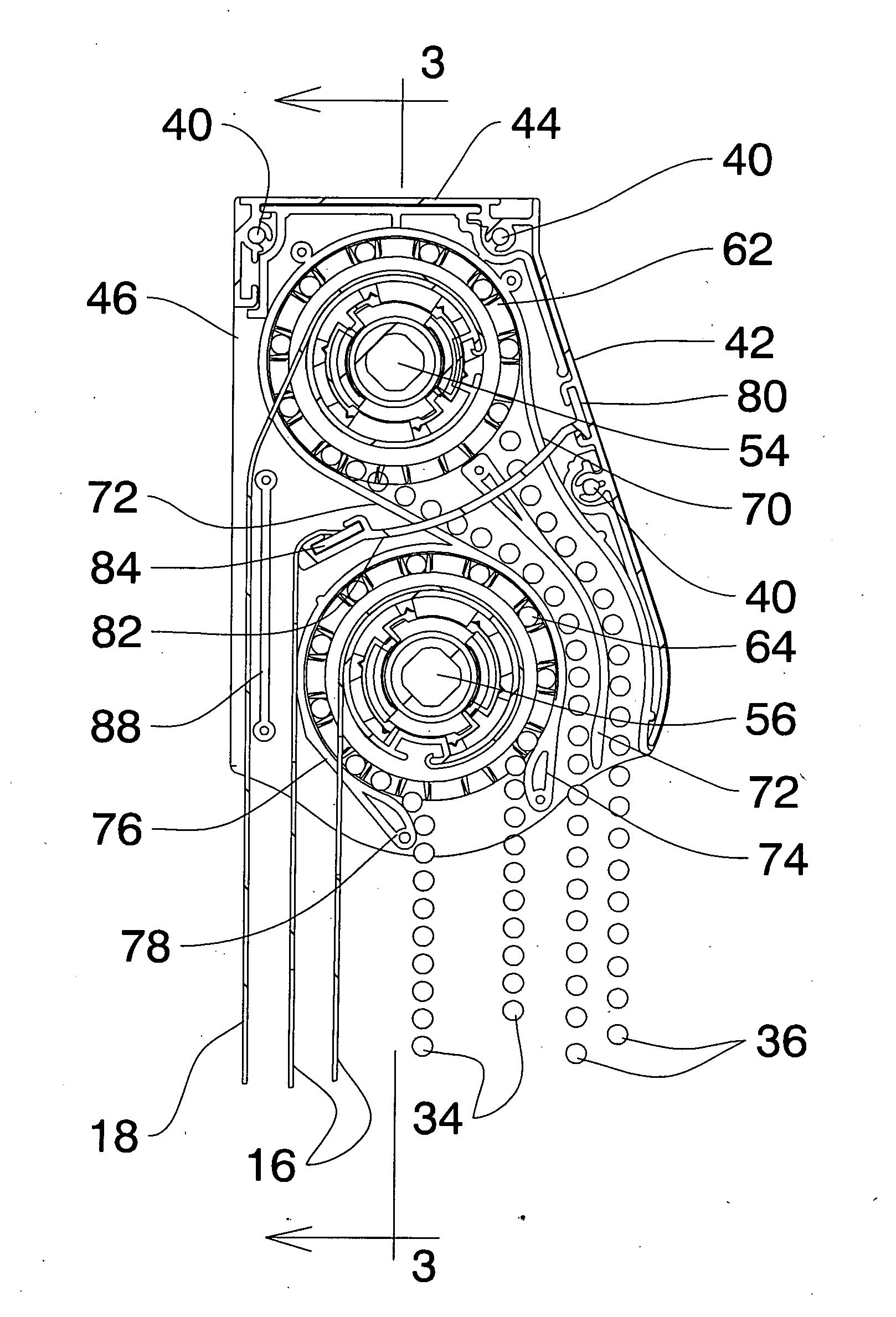
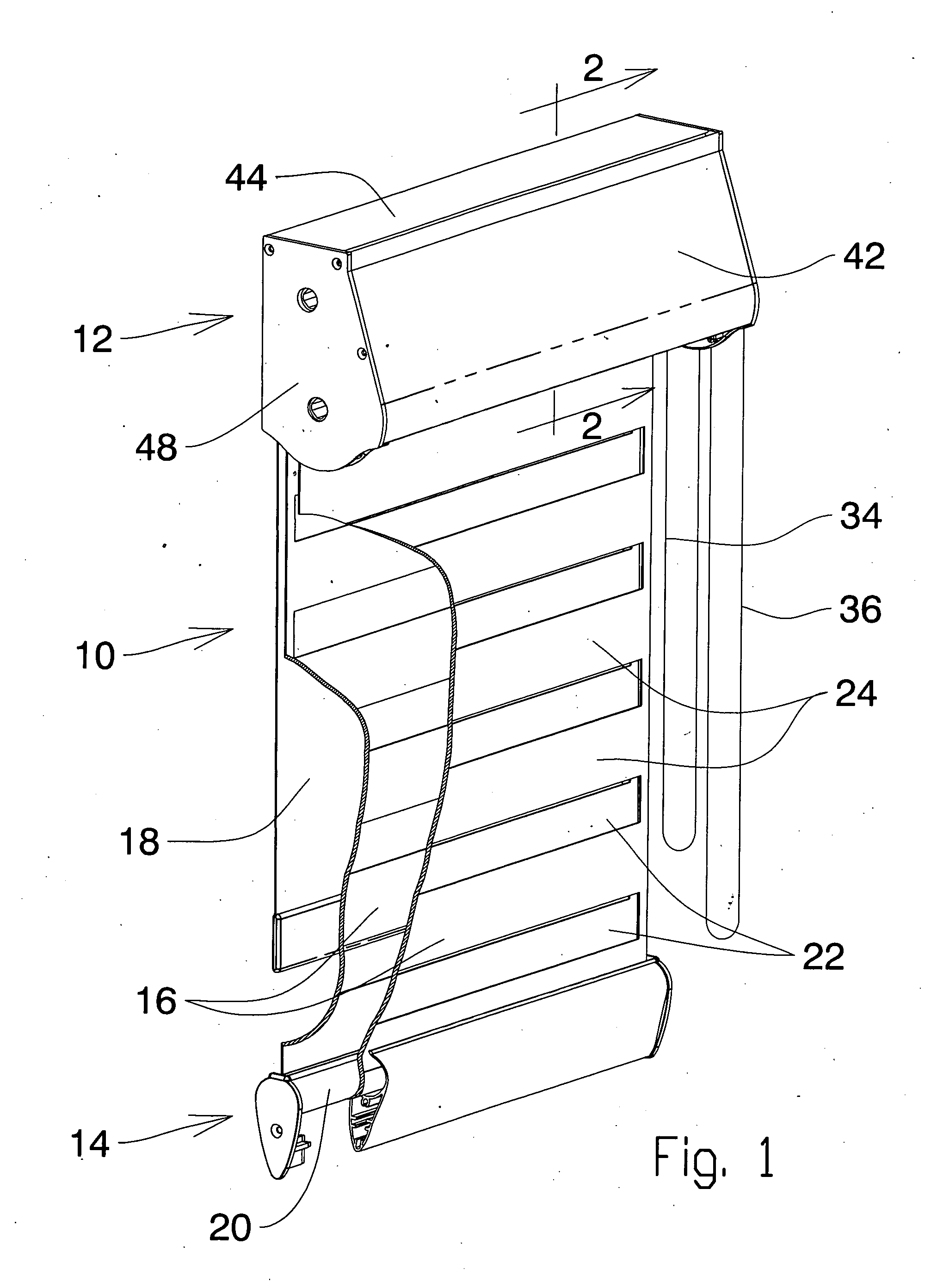
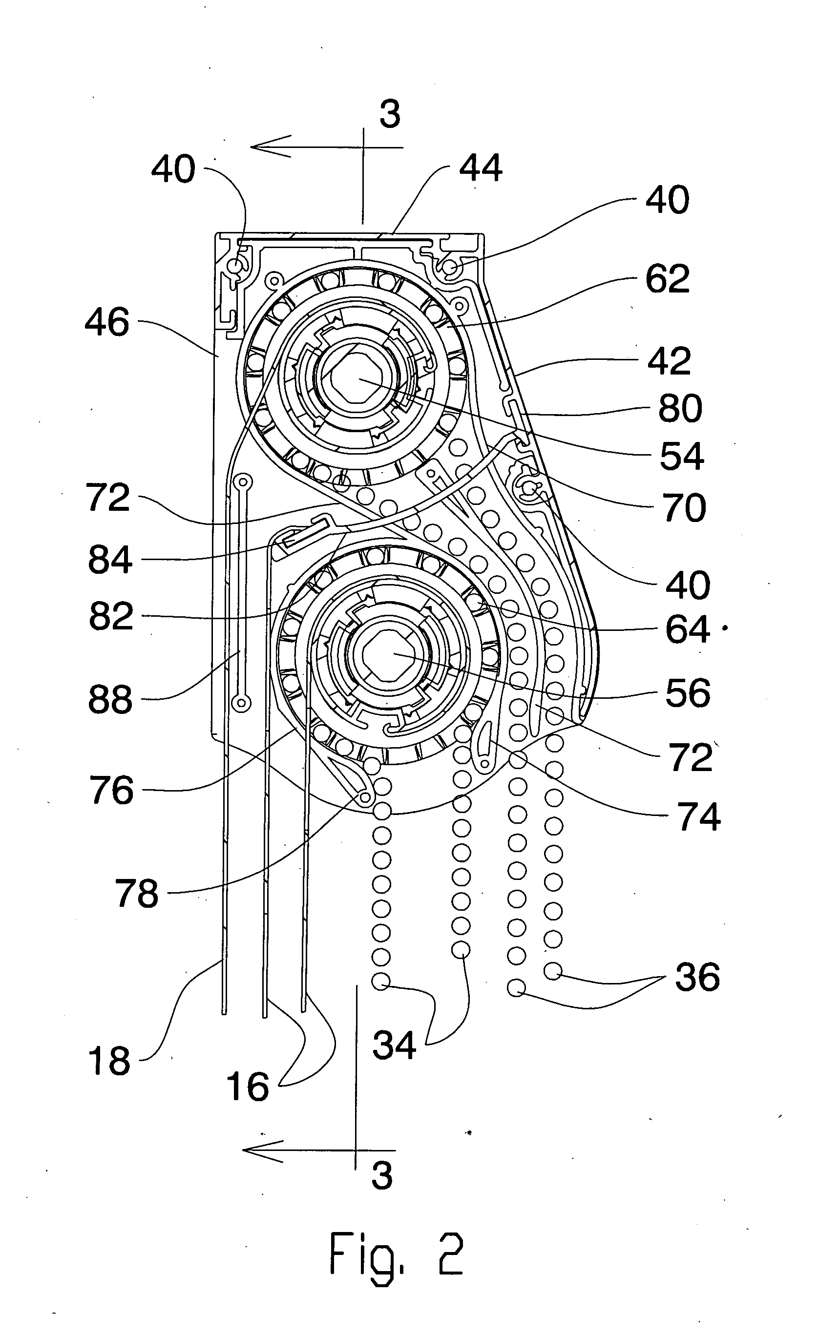
[0051]It will be seen that the blind illustrated generally as (10), comprises a head rail (12) and a bottom rail (14). The blind is typically located over a building opening such as a window.

[0052]The blind, in this first embodiment, provides a first or lower looped translucent blind panel (16) and a second or upper opaque blind panel (18). It will be seen that the first and second blind panels are supported so as to hang vertically. The second panel (18) has the usual bottom rail.

[0053]The first or lower blind is located in a lower region of the head rail, and is the lower blind.

[0054]The second blind panel is located in an upper region of the head rail, and is the upper blind.

[0055]First blind panel (16) is a continuous strip which passes around a bottom rail roller (20) in the bottom rail (14), and the free end is secured back up in the head rail (to be described below), so as to hold the looped panel in position.

[0056]As shown the front blind panel in this embodiment is a loop, ...


PUM


Abstract

A blind for a building opening, and having; an upper blind roller, located in an upper region of the head rail, a lower blind attachment located in a lower region of the head rail, an upper blind stored on the upper blind roller, a lower blind stored on the lower blind attachment, upper and lower blind control mechanism to operate the blinds and the upper blind roller being located with an upper axis along an upper plane in the head rail and the lower blind attachment is located on a lower axis along a lower plane within the head rail, the axes being displaced vertically from one another, and in which the upper blind depends down beside a predetermined side of the lower blind attachment, and in which the lower blind depends down alongside said upper blind, so as to provide a head rail having a slim, aesthetically pleasing profile.

Description

[0001]This application is a Continuation in Part of application Ser. No. ______, Filed Apr. 20, 2012, entitled Blind Assembly with Two Blind Headrails, Inventor Mario, M Marocco which was a Continuation in part of application Ser. No. 13 / 374,952 filed Jan. 25, 2012, title Blind Head Rail with Control Guides, Inventor Mario M Marocco, which was a Continuation-in-Part of application Ser. No. 13 / 067,189 filed May 16, 2011, title Double Blind and Head Rail, Inventor Mario M Marocco. The invention relates to blinds for windows, in which there are at least two panels of blind material, which may hang double, The panels can be adjusted for various light and shade effects, and can provide substantially complete black out if required, or can be rolled up into a headrail.FIELD OF THE INVENTIONBackground of the Invention[0002]In the past, conventional blinds for windows have typically been either venetian style blinds with transverse strips, or so called vertical blinds. These blinds could hav...

Claims


Application Information

Patent Timeline
Patent Type & Authority Applications(United States)
IPC IPC(8): E06B9/44
CPCE06B9/40E06B9/50E06B2009/2423E06B2009/2452E06B2009/405E06B2009/2405E06B9/24E06B9/44E06B9/78E06B2009/583E06B2009/587E06B2009/785
Inventor MAROCCO, MARIO M.
Owner MAXXMAR
Why Eureka
Try Eureka