Antenna with Multiple Resonating Conditions

a technology of resonating conditions and antennas, applied in the field of resonant antennas with multiple resonating conditions, can solve problems such as the limitation of its application rang

Active Publication Date: 2012-11-29
WISTRON NEWEB
View PDF5 Cites 19 Cited by
  • Summary
  • Abstract
  • Description
  • Claims
  • Application Information

AI Technical Summary

Problems solved by technology

Although the dual-band antenna 20 can achieve dual resonating conditions, for a wireless communication system with broad bandwidth, such as lon

Method used


Image

  • Antenna with Multiple Resonating Conditions
  • Antenna with Multiple Resonating Conditions
  • Antenna with Multiple Resonating Conditions

Examples


Embodiment Construction

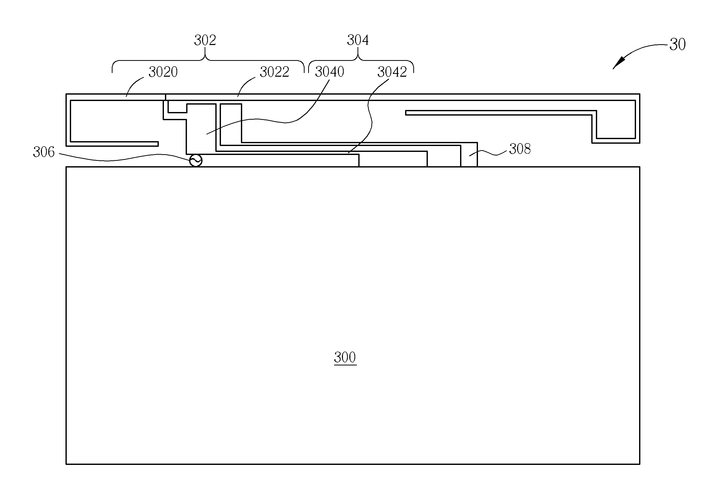
[0023]Please refer to FIG. 3, which is a schematic diagram of an antenna 30 according to an embodiment of the present invention. The antenna 30 has multiple resonating conditions, and includes a grounding element 300, a radiating element 302, a connection element 304, a feed-in element 306 and a radiating-condition generating element 308. The grounding element 300 is electrically connected to a ground for providing grounding. The radiating element 302 is composed of a first radiator 3020 and a second radiator 3022 extending along different directions and with different lengths to provide two different radiation frequency bands. The connection element 304 is composed of a first branch 3040 and a second branch 3042. The first branch 3040 is connected to the radiating element 302 and the feed-in element 306, and the second branch 3042 is connected to the feed-in element 306 and the grounding element 302. Therefore, comparing FIG. 3 with FIG. 2, structures of the antenna 30 and the dual...


PUM


Abstract

An antenna with multiple resonating conditions includes a grounding element electrically connected to a ground, a radiating element, a connection element electrically connected between the grounding element and the radiating element, a feed-in element electrically connected between the connection element and the grounding element for receiving feed-in signals, and a radiating-condition generating element electrically connected to the grounding element and extending from the grounding element to the radiating element.

Description

BACKGROUND OF THE INVENTION[0001]1. Field of the Invention[0002]The present invention relates to an antenna with multiple resonating conditions, and more particularly, to an antenna generating multiple resonating conditions with one or more radiating-condition generating elements connected to ground, to achieve broadband operations.[0003]2. Description of the Prior Art[0004]An antenna is used for transmitting or receiving radio waves, to communicate or exchange wireless signals. An electronic product with a wireless communication function, such as a laptop, a personal digital assistant (PDA), usually accesses a wireless network through a built-in antenna. Therefore, for facilitating the user to access the wireless communication network more easily, an ideal antenna should have a wide bandwidth and a small size to meet the trends of compact electronic products within a permitting range, so as to integrate the antenna into a portable wireless communication equipment.[0005]In the prior...

Claims


Application Information

Patent Timeline
IPC IPC(8): H01Q1/36H01Q5/10
CPCH01Q1/243H01Q5/378H01Q5/371H01Q9/42
Inventor YEN, LI-JEANLI, CHIA-TIEN
Owner WISTRON NEWEB
Why Eureka
Try Eureka