Intake and Exhaust Method and A Structure Utilizing the Same

a technology of intake and exhaust, which is applied in the direction of ventilation systems, heating types, lighting and heating apparatuses, etc., can solve the problems of turbulence generated, waste of energy, and insufficient heat in the interior space, and achieve the effect of improving air exchange rate and improving air exchange capacity

Inactive Publication Date: 2012-11-29
NAT PINGTUNG UNIV OF SCI & TECH
View PDF21 Cites 8 Cited by
  • Summary
  • Abstract
  • Description
  • Claims
  • Application Information

AI Technical Summary

Benefits of technology

[0009]It is therefore another objective of this invention to provide an intake and exhaust structure with enhanced air exchange capability.
[0010]It is yet another objective of this invention to provide an intake and exhaust structure that can adjust the direction thereof and therefore attain better air exchange rate.

Problems solved by technology

However, the heat in the interior space may not rise quickly enough when the temperature of the heat is not high enough.
Thus, electric power or similar energies will be needed to drive the exhaust ventilation device, resulting in a waste of energy.
Furthermore, the air outlet 92 of the duct 9 usually has an even periphery, which results in turbulence generated by interaction between the rising heat and the wind.
As a result, the wind-pulling effect is deteriorated.

Method used


Image

  • Intake and Exhaust Method and A Structure Utilizing the Same
  • Intake and Exhaust Method and A Structure Utilizing the Same
  • Intake and Exhaust Method and A Structure Utilizing the Same

Examples


Embodiment Construction

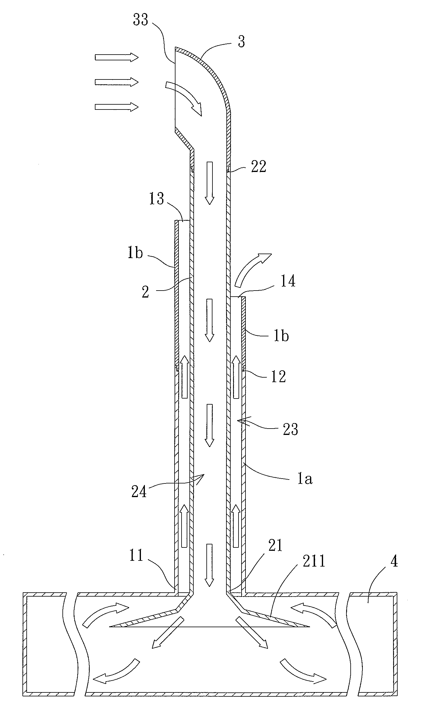
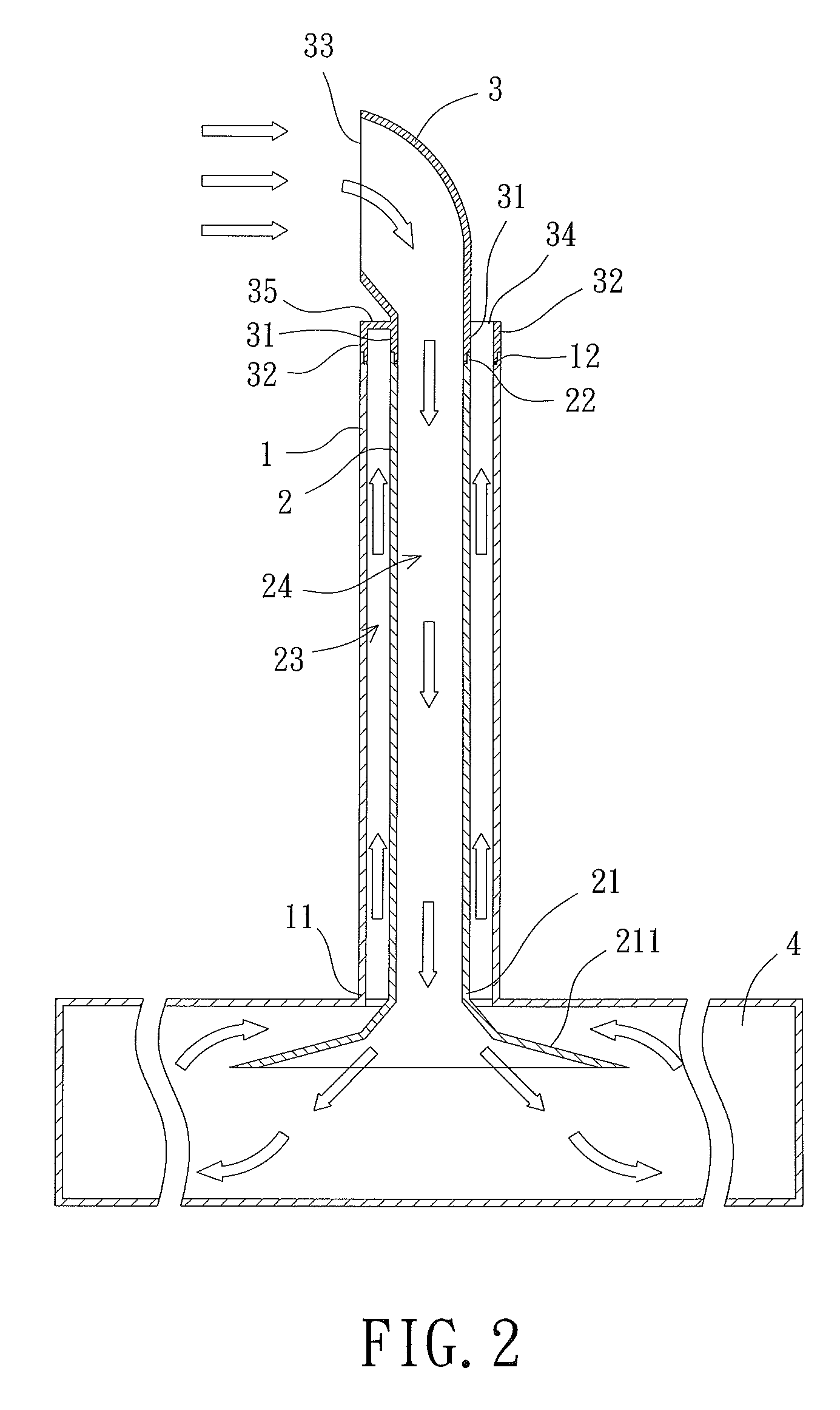
[0017]Referring to FIG. 2, an intake and exhaust structure using an intake and exhaust method is disclosed according to a first embodiment of the invention. The intake and exhaust structure includes an outer duct 1, an inner duct 2 and an air-guiding cover 3. The outer duct 1 has an air channel and may have a cross section in any shape, such as a circular shape adopted in this embodiment. In addition, the outer duct 1 has a first end 11 and a second end 12, and the inner duct 2 has a first end 21 and a second end 22. The air-guiding cover 3 is coupled with the second ends 12 and 22 of the outer duct 1 and the inner duct 2.

[0018]The inner duct 2 is disposed in the outer duct 1 and may have a cross section in any shape, such as a circular shape adopted in this embodiment. A circular air channel 23 is defined between the outer duct 1 and the inner duct 2. The inner duct 2 further comprises an intake air channel 24. In addition, the inner duct 2 may have an air-spreading member 211 at t...


PUM


Abstract

An intake and exhaust structure includes an outer duct, an inner duct and an air-guiding cover. The outer duct has a first end and a second end. The inner duct has a first end, a second end and an intake air channel. The inner duct is disposed in the outer duct, and a circular air channel is defined between the inner and outer ducts. The air-guiding cover has an inner wall and an air inlet at two ends thereof, wherein the inner wall is coupled with the second end of the inner duct.

Description

BACKGROUND OF THE INVENTION[0001]1. Field of the Invention[0002]The present invention generally relates to an intake and exhaust method and an intake and exhaust structure utilizing the same and, more particularly, to an intake and exhaust method that performs an intake and exhaust operation using natural wind, as well as an intake and exhaust structure utilizing the same.[0003]2. Description of the Related Art[0004]Intake and exhaust structures are commonly constructed in a variety of infrastructures, industrial architectures or buildings. An intake and exhaust structure of a building can provide air exchange for an interior space of the building by drawing external air into the interior space. In such a manner, waste gas or heat of the building can be expelled. Generally, the intake and exhaust structure has a duct for expelling airs.[0005]Referring to FIG. 9, a conventional duct 9 is shown. The duct 9 is in a tube form and has an air channel 91 and an air outlet 92. The duct 9 ha...

Claims


Application Information

Patent Timeline
Patent Type & Authority Applications(United States)
IPC IPC(8): F24F7/04
CPCE04F17/04F24F7/08F24F2221/52F24F2007/004F24F2007/001
Inventor TAI, CHANG-HSIENLO, SHI-WEICHANG, LIANG-JI
Owner NAT PINGTUNG UNIV OF SCI & TECH
Why Eureka
Try Eureka