Sensor for use in protective headgear

a headgear and sensor technology, applied in the field of protective headgear, can solve the problems of obvious disadvantages of conventional approaches

Active Publication Date: 2012-12-06
THL HLDG
View PDF10 Cites 29 Cited by
  • Summary
  • Abstract
  • Description
  • Claims
  • Application Information

AI Technical Summary

Problems solved by technology

The disadvantages of conventional approaches will be evident to one skilled in the art when presented the disclosure that follows.

Method used


Image

  • Sensor for use in protective headgear
  • Sensor for use in protective headgear
  • Sensor for use in protective headgear

Examples


Embodiment Construction

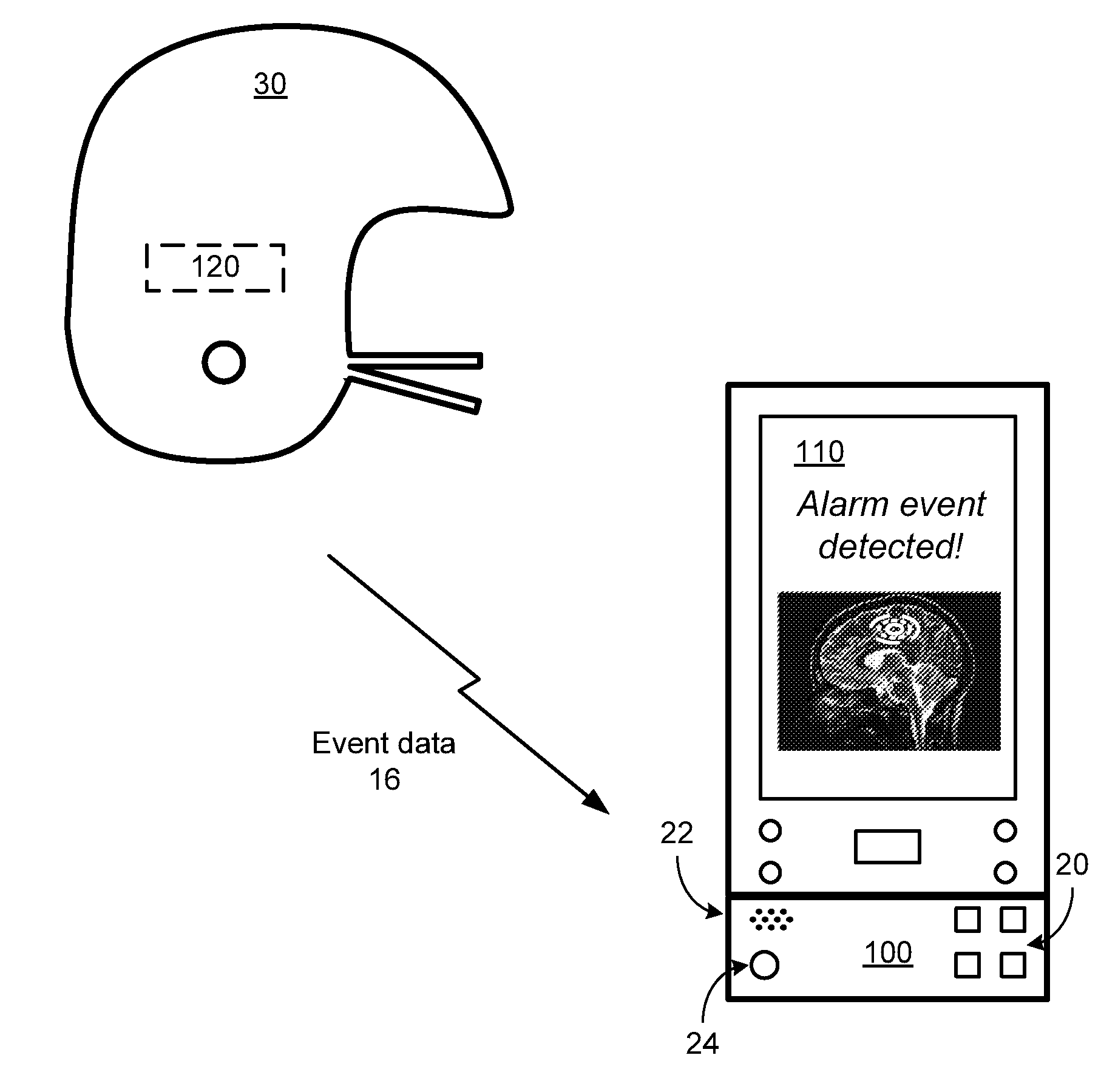
[0055]FIG. 1 presents a pictorial representation of a system for monitoring protective headgear in accordance with an embodiment of the present invention. In particular, a handheld communication device 110, such as a smart phone, digital book, netbook, personal computer with wireless data communication or other wireless communication device includes a wireless transceiver for communicating over a long range wireless network such as a cellular, PCS, CDMA, GPRS, GSM, iDEN or other wireless communications network and / or a short-range wireless network such as an IEEE 802.11 compatible network, a Wimax network, another wireless local area network connection or other communications link. Handheld communication device 110 is capable of engaging in wireless communications such as sending and receiving telephone calls and / or wireless data in conjunction with text messages such as emails, short message service (SMS) messages, pages and other data messages that may include multimedia attachmen...


PUM

PropertyMeasurementUnit
massaaaaaaaaaa
elasticaaaaaaaaaa
impact thresholdaaaaaaaaaa

Abstract

A sensor includes a housing and a mass, suspended in the housing. The motion of the mass emulates dynamic behavior of a brain of the wearer along a plurality of axes. At least one sensing element is coupled to generate sensor data based on the motion of the mass, in response to an impact to a protective helmet.

Description

CROSS REFERENCE TO RELATED APPLICATIONS[0001]The present application claims priority under 35 USC 119 to the provisionally filed application, METHOD, SYSTEM, DEVICE AND PROTECTIVE HEADGEAR, having Ser. No. 61 / 623,189, filed on Apr. 12, 2012; the contents of which is expressly incorporated herein in its entirety by reference thereto.[0002]The present application claims priority under 35 USC 119 to the provisionally filed application, METHOD, SYSTEM AND WIRELESS DEVICE FOR MONITORING PROTECTIVE HEADGEAR, having Ser. No. 61 / 558,764, filed on Nov. 11, 2011; the contents of which is expressly incorporated herein in its entirety by reference thereto.[0003]The present application also claims priority under 35 USC 120 as a continuation in part to the U.S. publication number 2011 / 0210847, entitled “SYSTEM AND WIRELESS DEVICE FOR LOCATING A REMOTE OBJECT”, having Ser. No. 12 / 713,316 filed on Feb. 26, 2010; the contents of which is expressly incorporated herein in its entirety by reference the...

Claims


Application Information

Patent Timeline
Patent Type & Authority Applications(United States)
IPC IPC(8): G01N3/30A42B3/00
CPCY10S2/909A42B3/046
Inventor HOWARD, JOHN W.CUTLER, RICHARD
Owner THL HLDG
Why Eureka
Try Eureka