Eureka AIR delivers breakthrough ideas for toughest innovation challenges, trusted by R&D personnel around the world.

Electrical connector with power plug and power socket

Inactive Publication Date: 2012-12-06
FU TAI HUA IND SHENZHEN +1
View PDF22 Cites 6 Cited by
  • Summary
  • Abstract
  • Description
  • Claims
  • Application Information

AI Technical Summary

Benefits of technology

[0004]A power wire is used for connecting an electronic device and a power supply, such that the electronic device is powered by the power supply. The power wire generally has a first plug and a second plug on opposite ends thereof, and the first plug and the second plug are exposed to the outside environment without any protective sleeve. However, when the first plug is connected to the power supply, and the second plug is not connected to anything, electricity from the power supply may pass to the outside via the second plug. Under damp or in certain other conditions, or by simple mishandling, accidents caused by electric shock may occur.

Problems solved by technology

Under damp or in certain other conditions, or by simple mishandling, accidents caused by electric shock may occur.

Method used


Image

  • Electrical connector with power plug and power socket
  • Electrical connector with power plug and power socket
  • Electrical connector with power plug and power socket

Examples


Embodiment Construction

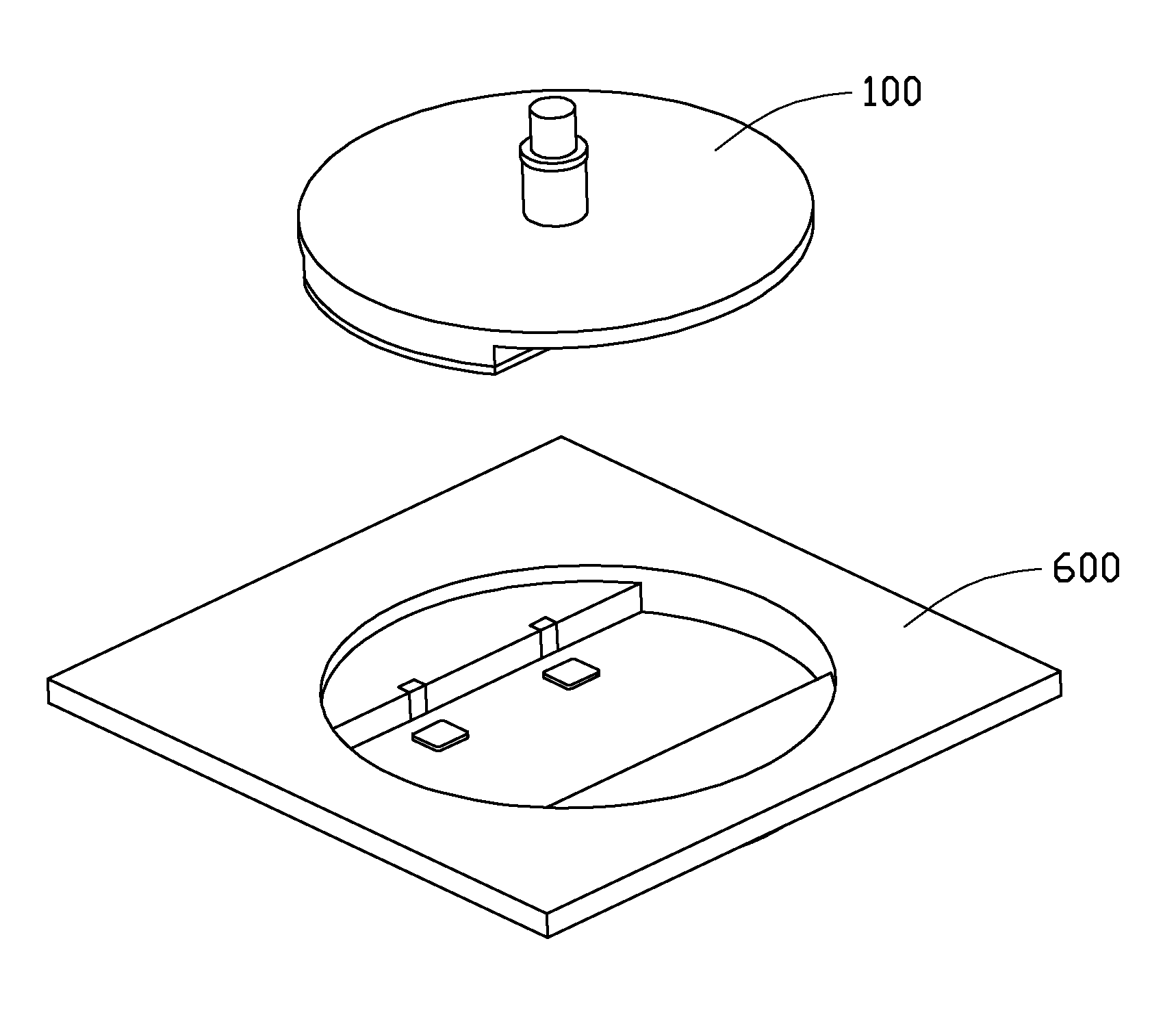
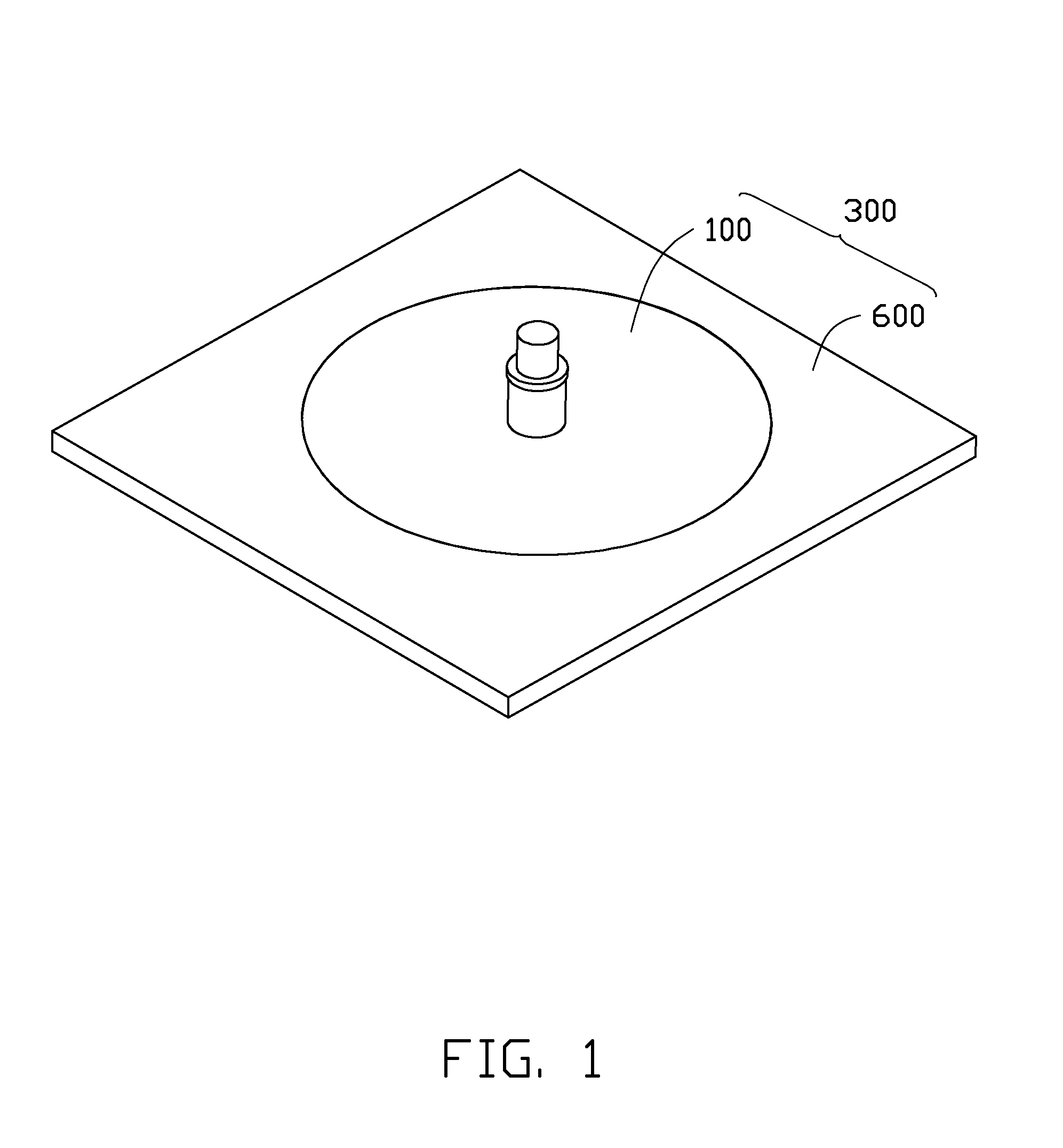
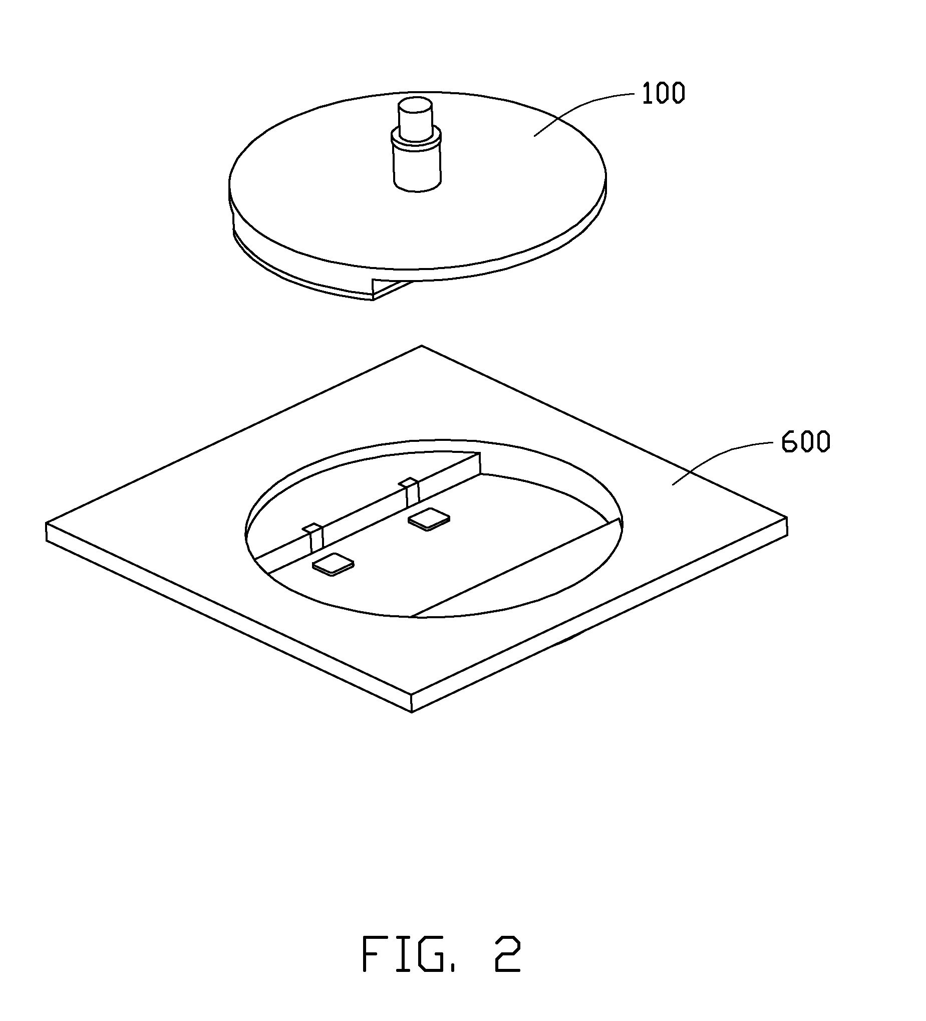
[0014]Referring to FIGS. 1 and 2, an embodiment of an electrical connector 300 includes a power plug 100 and a power socket 600. In use, the power socket 600 is positioned on an electronic device (not shown), and the power plug 100 is electrically connected to a power wire (not shown) which is connected to a power supply (not shown).

[0015]Referring to FIGS. 3 through 5, the power plug 100 includes a housing 10, two magnetic members 20, two resilient pieces 30, two plug contacts 40, and a conductive member 50. It should be understood that, the power plug 100 may include three or more plug contacts 40, and correspondingly, the power plug 100 would have three or more magnetic members 20 and three or more resilient pieces 30.

[0016]The housing 10 includes a main body 11 and a cover 15 connected to the main body 11. The main body 11 and the cover 15 are made of insulating materials, such as plastic. The main body 11 includes a circular connecting portion 113, a frame portion 115, and a po...


PUM


Abstract

An electronic device includes a power plug and a power socket coupled to the power plug. The power plug includes a housing, two plug contacts, one conductive member, two conductive resilient pieces, and two magnetic members. The conductive resilient pieces are positioned in the housing, and are electrically connected to the conductive member. The magnetic members are positioned in the housing, and opposite to the at least two conductive resilient pieces. The power socket includes an inner housing, two socket contacts, and two metal pieces. The inner housing defines an assembly groove to receive the power plug. The metal pieces are positioned in the assembly groove of the inner housing, and are opposite to the magnetic members, such that a magnetic attraction force exerted between the metal pieces and the magnetic member actuates the power plug.

Description

BACKGROUND[0001]1. Technical Field[0002]The present disclosure generally relates to electrical connectors, and particularly, to an electrical connector with a power plug and a power socket.[0003]2. Description of the Related Art[0004]A power wire is used for connecting an electronic device and a power supply, such that the electronic device is powered by the power supply. The power wire generally has a first plug and a second plug on opposite ends thereof, and the first plug and the second plug are exposed to the outside environment without any protective sleeve. However, when the first plug is connected to the power supply, and the second plug is not connected to anything, electricity from the power supply may pass to the outside via the second plug. Under damp or in certain other conditions, or by simple mishandling, accidents caused by electric shock may occur.[0005]Therefore, there is room for improvement within the art.BRIEF DESCRIPTION OF THE DRAWING[0006]The components in the...

Claims


Application Information

Patent Timeline
IPC IPC(8): H01R11/30
CPCH01R13/6205
Inventor LEE, CHUN-LANGDAI, BIN
Owner FU TAI HUA IND SHENZHEN
Why Eureka
Eureka Blog
Learn More