Eureka AIR delivers breakthrough ideas for toughest innovation challenges, trusted by R&D personnel around the world.

Regenerative suspension with accumulator systems and methods

Active Publication Date: 2012-12-13
PHYSICS LAB OF LAKE HAVASU
View PDF1 Cites 40 Cited by
  • Summary
  • Abstract
  • Description
  • Claims
  • Application Information

AI Technical Summary

Benefits of technology

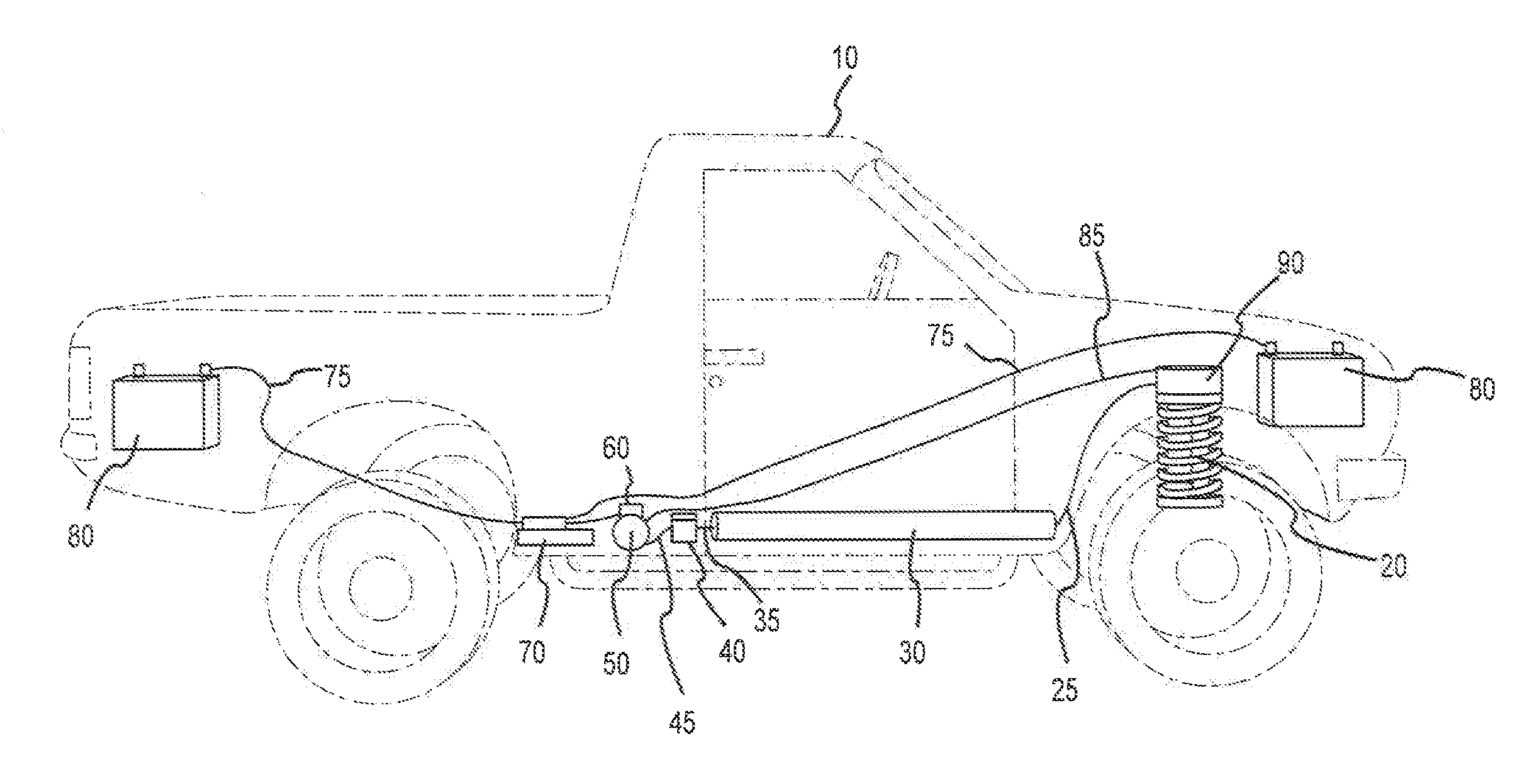
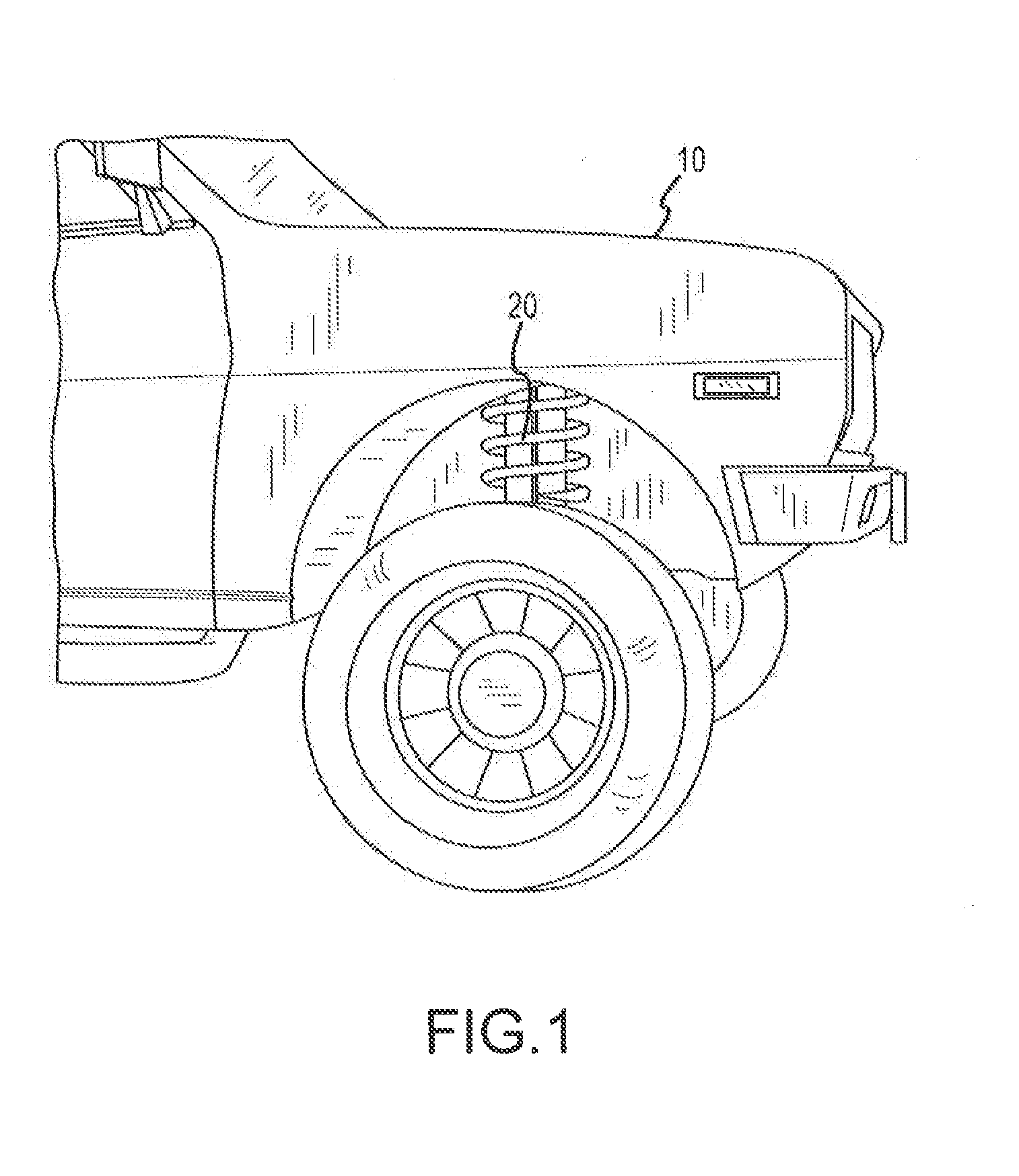
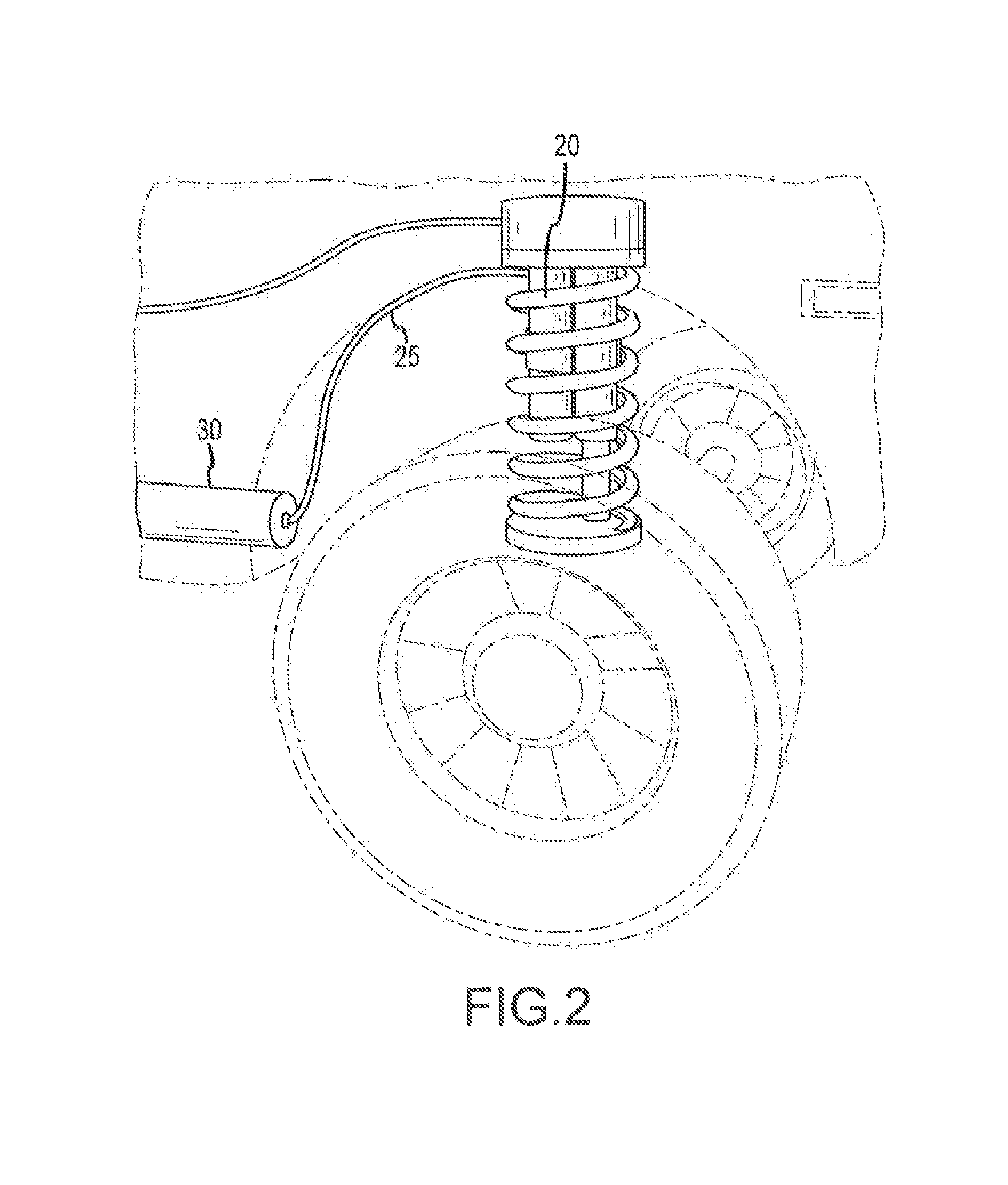
[0004]In exemplary embodiments, a regenerative suspension system replaces or complements a standard shock absorber on a vehicle. A pump attaches via a hose to a central accumulator cylinder that is mounted on a vehicle. Pressurized fluid, air, or other material charges the accumulator. The accumulator is coupled to a motor via a solenoid valve, or other automatic pressure relief valve, as in air brake system

Problems solved by technology

Hybrids, semi-tractors and their trailers, locomotives, military and other vehicles have few ways to perform work without burning fuel.
In our society, the cost of fuel has been growing more expensive every month.
For example, because variations on driving surfaces are subtle, existing systems do not produce enough hydraulic or pneumatic pressure to efficiently operate motors and electric generators.

Method used


Image

  • Regenerative suspension with accumulator systems and methods
  • Regenerative suspension with accumulator systems and methods
  • Regenerative suspension with accumulator systems and methods

Examples


Embodiment Construction

[0017]The detailed description of exemplary embodiments herein makes reference to the accompanying Figures, which show the exemplary embodiments by way of illustration and its best mode. While these exemplary embodiments are described in sufficient detail to enable those skilled in the art to practice the invention, it should be understood that other embodiments may be realized and that logical and mechanical changes may be made without departing from the spirit and scope of the invention. Thus, the detailed description herein is presented for purposes of illustration only and not of limitation. For example, the steps recited in any of the method or process descriptions may be executed in any order and are not limited to the order presented. Moreover, any of the functions or steps may be outsourced to or performed by one or more third parties. Furthermore, any reference to singular includes plural embodiments, and any reference to more than one component may include a singular embod...


PUM


Abstract

In exemplary embodiments, a regenerative suspension system replaces or complements a standard shock absorber on a vehicle. A pump attaches via a hose to a central accumulator cylinder that is mounted on a vehicle. Pressurized fluid, air, or other material charges the accumulator. The Pressurized fluid, air, or other material is controllably released via a valve in order to perform work.

Description

CROSS-REFERENCE TO RELATED. APPLICATIONS[0001]This application is a continuation-in-part of application Ser. No. 12 / 842,765, entitled REGENERATIVE SUSPENSION WITH ACCUMULATOR SYSTEMS AND METHODS, filed Jul. 23, 2010, which is a continuation-in-part of application Ser. No. 12 / 206,082 (U.S. Pat. No. 7,938,217, issued May 10, 2011), entitled REGENERATIVE SUSPENSION WITH ACCUMULATOR SYSTEMS AND METHODS, filed Sep. 8, 2008, which claims the benefit of U.S. Provisional Patent Application Ser. No. 61 / 035,494, entitled HYDRAULIC / AIR SUSPENSION ENERGY RETURN, filed Mar. 11, 2008, each of which are incorporated by reference herein in their entireties.BACKGROUND OF THE INVENTION[0002]Hybrids, semi-tractors and their trailers, locomotives, military and other vehicles have few ways to perform work without burning fuel. In our society, the cost of fuel has been growing more expensive every month. Many people have switched to driving hybrids in order to save money on fuel. In some hybrids and othe...

Claims


Application Information

Patent Timeline
IPC IPC(8): H02J7/00
CPCB60K25/10F03G7/08B60G13/14B60G2500/30B60G17/021B60G2300/60H02J7/0052H02J7/00
Inventor STANSBURY, III, JAMES A.
Owner PHYSICS LAB OF LAKE HAVASU
Why Eureka
Eureka Blog
Learn More