Method of operating a synthetic vision system in an aircraft

a synthetic vision and aircraft technology, applied in the direction of navigation instruments, instruments, transportation and packaging, etc., can solve the problem that the current synthetic vision system is limited to providing the crew

Active Publication Date: 2013-01-03
GENERAL ELECTRIC CO
View PDF3 Cites 16 Cited by
  • Summary
  • Abstract
  • Description
  • Claims
  • Application Information

AI Technical Summary

Problems solved by technology

Current synthetic vision systems are limited...

Method used


Image

  • Method of operating a synthetic vision system in an aircraft
  • Method of operating a synthetic vision system in an aircraft
  • Method of operating a synthetic vision system in an aircraft

Examples


Embodiment Construction

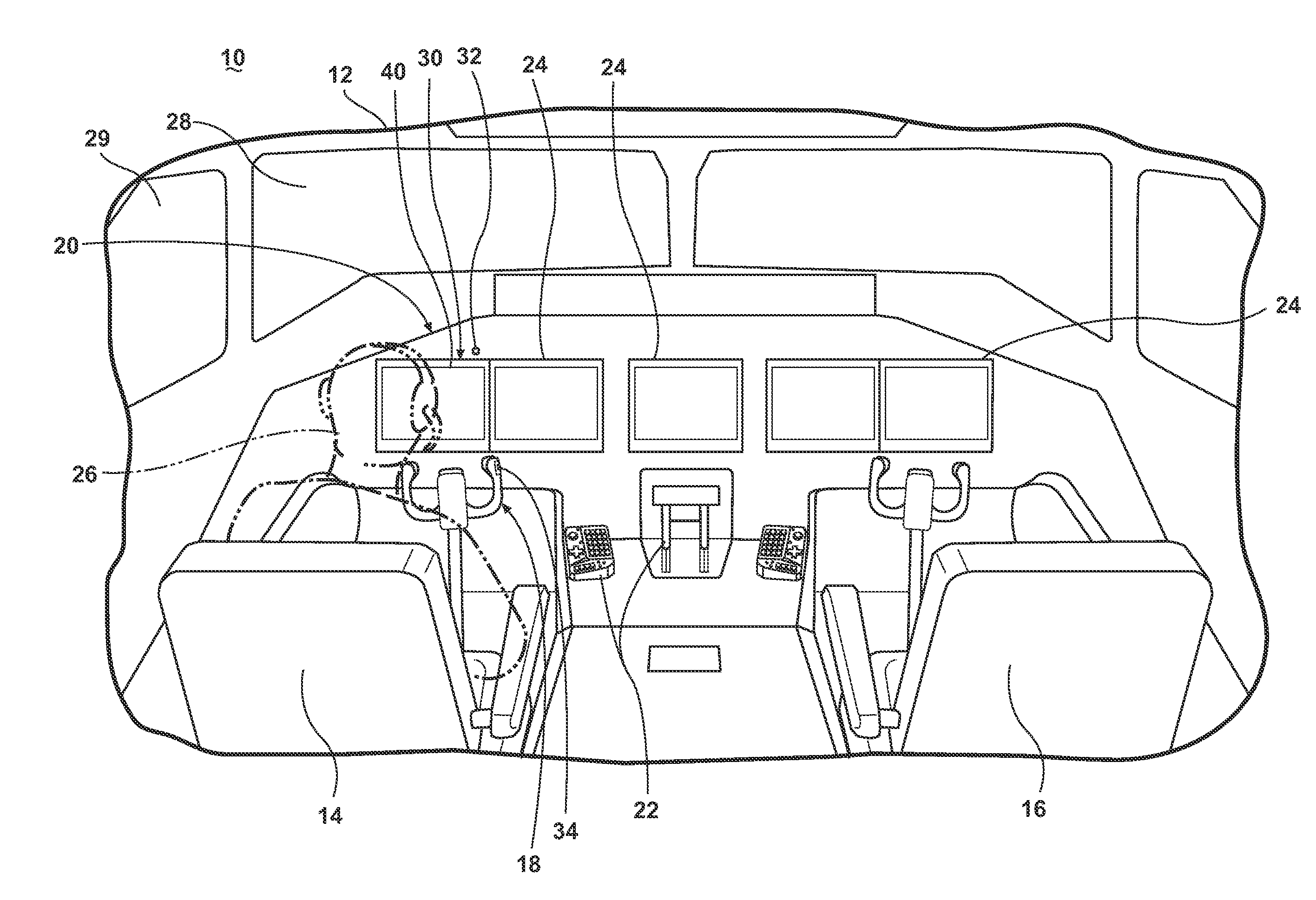
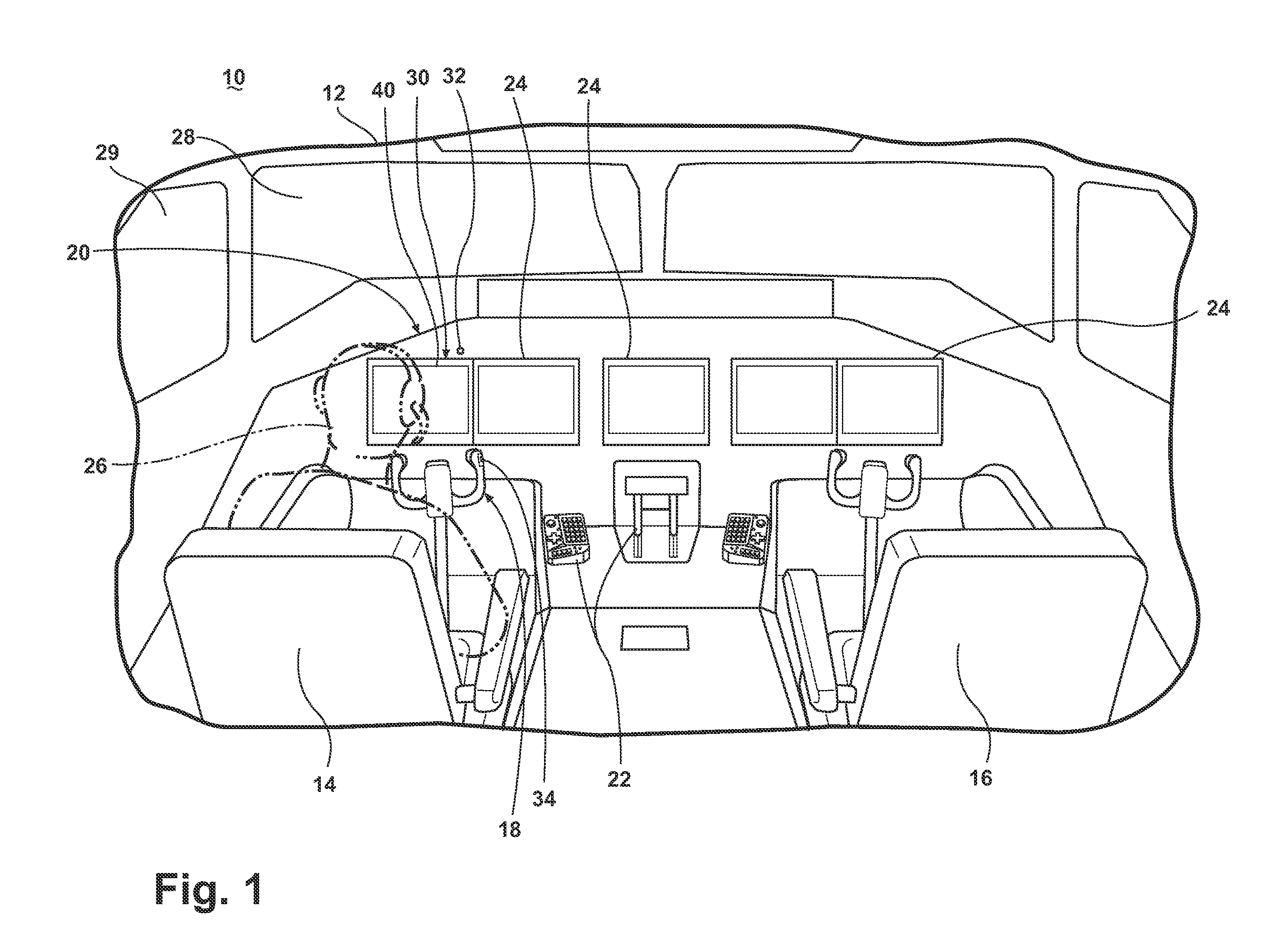
[0008]FIG. 1 illustrates a portion of an aircraft 10 having a cockpit 12 with a pilot seat 14, a co-pilot seat 16, an aircraft control yoke 18, and a flight deck 20 having a number of flight controls 22 and multiple flight displays 24. The multiple flight displays 24 may include primary and secondary flight displays any of which may be used to display to the pilot and flight crew a wide range of aircraft, flight, navigation, and other information used in the operation and control of the aircraft. While a commercial aircraft has been illustrated it is contemplated that the invention may be used in any type of aircraft, for example, without limitation, fixed-wing, rotating-wing, rocket, personal aircraft, and military aircraft.

[0009]A pilot 26, sitting in the pilot seat 14 facing the flight deck 20, may utilize the yoke 18 as well as the other flight controls 22 to maneuver the aircraft 10. It is contemplated that a control stick or other control device may alternatively be installed ...


PUM


Abstract

A method of operating an aircraft comprising a cockpit with a flight deck having at least one flight display, a pilot's seat facing the flight deck, and a synthetic vision system producing a synthetic image for displaying on the at least one flight display.

Description

BACKGROUND OF THE INVENTION[0001]A contemporary aircraft may include the use of a synthetic vision system, which may present the crew with a display showing a computer generated representation of the world in front of the aircraft. Such a synthetic vision system improves the ability of a flight crew to orient themselves with respect to geographical terrain and obstacles and provides them with images corresponding to what they would actually see out of the windshield of the cockpit under clear visibility conditions. Such a system may be particularly useful when visibility is poor outside the aircraft. Current synthetic vision systems are limited to providing the crew with a forward looking view.BRIEF DESCRIPTION OF THE INVENTION[0002]In one embodiment, a method of operating an aircraft having a cockpit with a flight deck having at least one flight display, a pilot's seat facing the flight deck, and a synthetic vision system producing a synthetic image for displaying on the at least o...

Claims


Application Information

Patent Timeline
IPC IPC(8): G01C21/00
CPCG01C23/00B64D43/00G09B9/302G06F3/012
Inventor BURNS, TIMOTHY DONAL PAULKOLBE, DASHIELL MATTHEWSOVENS, NORMAN LEONARD
Owner GENERAL ELECTRIC CO
Why Eureka
Try Eureka