
Apparatus and method for displaying a synthetic vision system view direction

a synthetic vision and display method technology, applied in the field of aircraft displays, can solve the problems of impede or conflict with other symbols, more problems with displays, and less useful frustum lines

Active Publication Date: 2016-07-21
HONEYWELL INT INC
View PDF6 Cites 8 Cited by
  • Summary
  • Abstract
  • Description
  • Claims
  • Application Information

AI Technical Summary

Benefits of technology

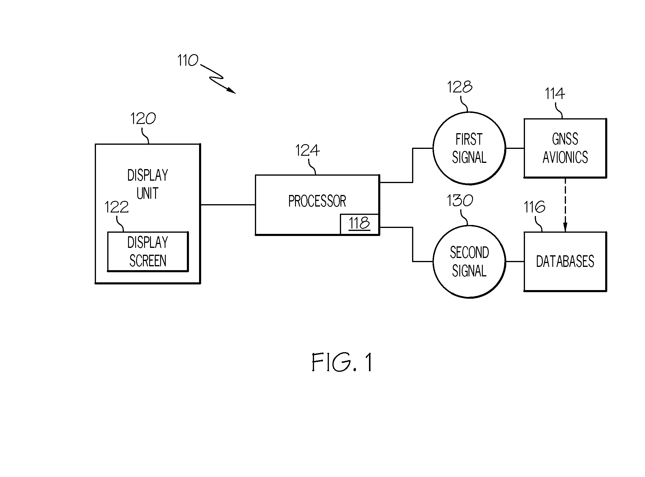
This patent describes a display system and method for helping aircraft pilots see the world around them. The system uses synthetic vision to create a virtual view of the world, which is then displayed on the aircraft's screen. The system can also display a compass to indicate the position of the aircraft, and can provide guidance on how to move around in the virtual space. Overall, this technology makes it easier for pilots to see what they're flying towards and helps improve safety during takeoff and landing.

Problems solved by technology

As such, representing the current flight path direction, for example, as a flight path marker, on a typical rotorcraft synthetic vision system (SVS) display typically presents more issues in comparison to the fixed wing aircraft.
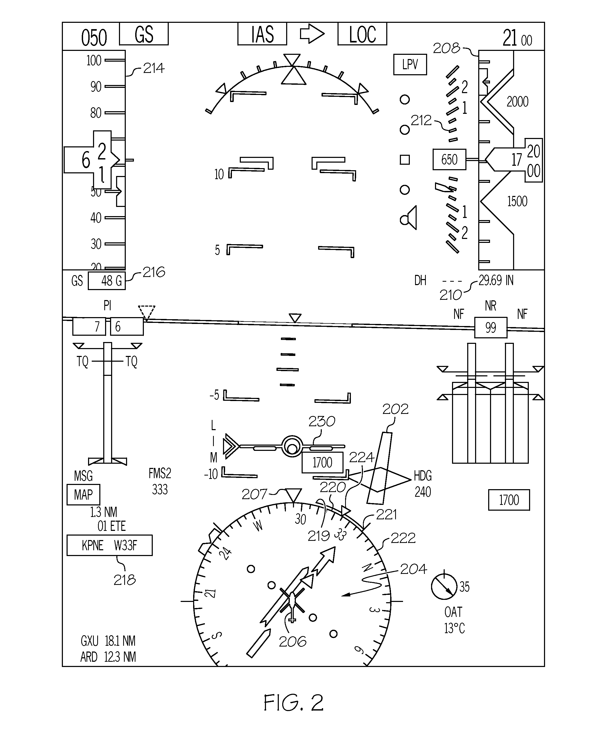
However, the frustum lines are less useful if the compass doesn't have a scale associated with it and can impede or conflict with other symbols displayed inside the compass.
For example, when the compass area contains lateral deviation symbology for both current and armed navigation (Nav) mode, adding frustum lines can cause difficulties in not only identifying the frustum lines but can interfere with the reading of navigation information.
In addition, simple frustum lines do not adequately provide awareness of the large differential between current track and heading conditions.

Method used


Image

  • Apparatus and method for displaying a synthetic vision system view direction
  • Apparatus and method for displaying a synthetic vision system view direction
  • Apparatus and method for displaying a synthetic vision system view direction

Examples


Embodiment Construction

[0016]The following detailed description is merely illustrative in nature and is not intended to limit the embodiments of the subject matter or the application and uses of such embodiments. Any implementation described herein as exemplary is not necessarily to be construed as preferred or advantageous over other implementations. Furthermore, there is no intention to be bound by any expressed or implied theory presented in the preceding technical field, background, brief summary, or the following detailed description.

[0017]Those of skill in the art will appreciate that the various illustrative logical blocks, modules, circuits, and algorithm steps described in connection with the embodiments disclosed herein may be implemented as electronic hardware, computer software, or combinations of both. Some of the embodiments and implementations are described above in terms of functional and / or logical block components (or modules) and various processing steps. However, it should be appreciat...


PUM


Abstract

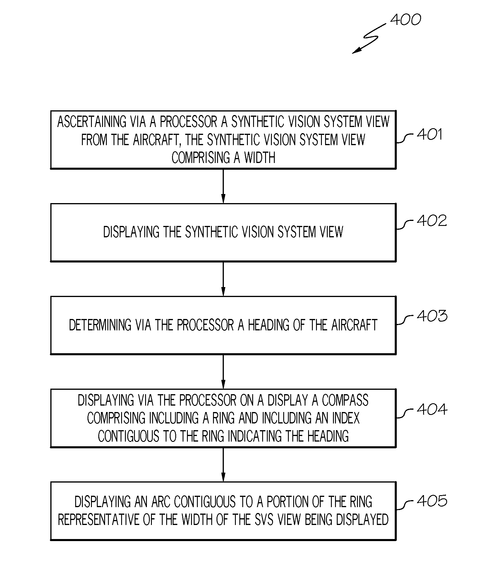
A system and method displays a synthetic vision system (SVS) image combined with a primary flight display (PFD) including a compass indicating the aircraft heading. An arc on or near the outer edge of the compass indicates the viewing frustum of the SVS view.

Description

TECHNICAL FIELD[0001]The exemplary embodiments described herein generally relates to aircraft displays and more particularly to helicopter synthetic vision system (SVS) displays.BACKGROUND[0002]Aircraft occasionally may have a flight path different than a heading, for example, when landing in a crosswind. Helicopter flying differs from fixed wing aircraft with significantly more vertical and lateral movement and dynamics, including a flight path often quite different than the heading of the helicopter.[0003]When a SVS image is displayed on the Primary Flight Display (PFD) and the SVS view may be centered at an angle other than the heading, the pilot needs to be able to quickly correlate the displayed SVS view to information in the compass. The compass is usually centered at the heading direction so as to correlated and fly according to ATC issued heading instructions. As such, representing the current flight path direction, for example, as a flight path marker, on a typical rotorcra...

Claims


Application Information

Patent Timeline
Patent Type & Authority Applications(United States)
IPC IPC(8): G01C23/00
CPCG01C23/005G05D1/10G01C23/00G08G5/0021
Inventor HARVEY, JASON F.HE, GANG
Owner HONEYWELL INT INC
Learn More