Foldable electric device

Inactive Publication Date: 2013-01-17
QUANTA COMPUTER INC
View PDF9 Cites 26 Cited by
  • Summary
  • Abstract
  • Description
  • Claims
  • Application Information

AI Technical Summary

Benefits of technology

[0011]The first member comprises a first chassis, a first cushion pad and a first magnetic component. The first cushion is retractable disposed on a surface of the second chassis. The first magnetic component is installed in the first chassis, and linked by the first cushion pad to synchronously move. The second member comprises a second chassis and a second magnetic component. The second magnetic component is installed in the second member. The pivot portion is used to pivot the first chassis and the second chassis. When the first chassis and the second chassis are covered with each other, with the magnetic effect between the fir

Problems solved by technology

However, no matter the top chassis and the bottom chassis are mutually rotated to open and close themselves, the cus

Method used


Image

  • Foldable electric device
  • Foldable electric device
  • Foldable electric device

Examples


first embodiment

[0040]Referring to FIG. 4 and FIG. 5, wherein FIG. 4 is a schematic view showing the foldable electric device under a reversely covering state according to the alternative of the present invention; and FIG. 5 is a schematic enlarged view showing the zone M3 of FIG. 4.

[0041]When the second chassis 410 reversely covers on the first chassis 310, and the operation interface 320 is opposite to the display screen 420, with the magnetic attraction force between the first magnetic component 350 and the second magnetic component 430, the first magnetic component 350 is moved towards the second magnetic component 430, and the first cushion pad 330 is driven to synchronously retract under the first surface 311 of the first chassis 310 along the Z axle direction. At this moment, the first end 381 of the linkage rod 380 is also driven by the first magnetic component 350 to rotate towards the D3 direction, and the second end 382 of the linkage rod 380 also synchronously rotates towards the D3 dir...

second embodiment

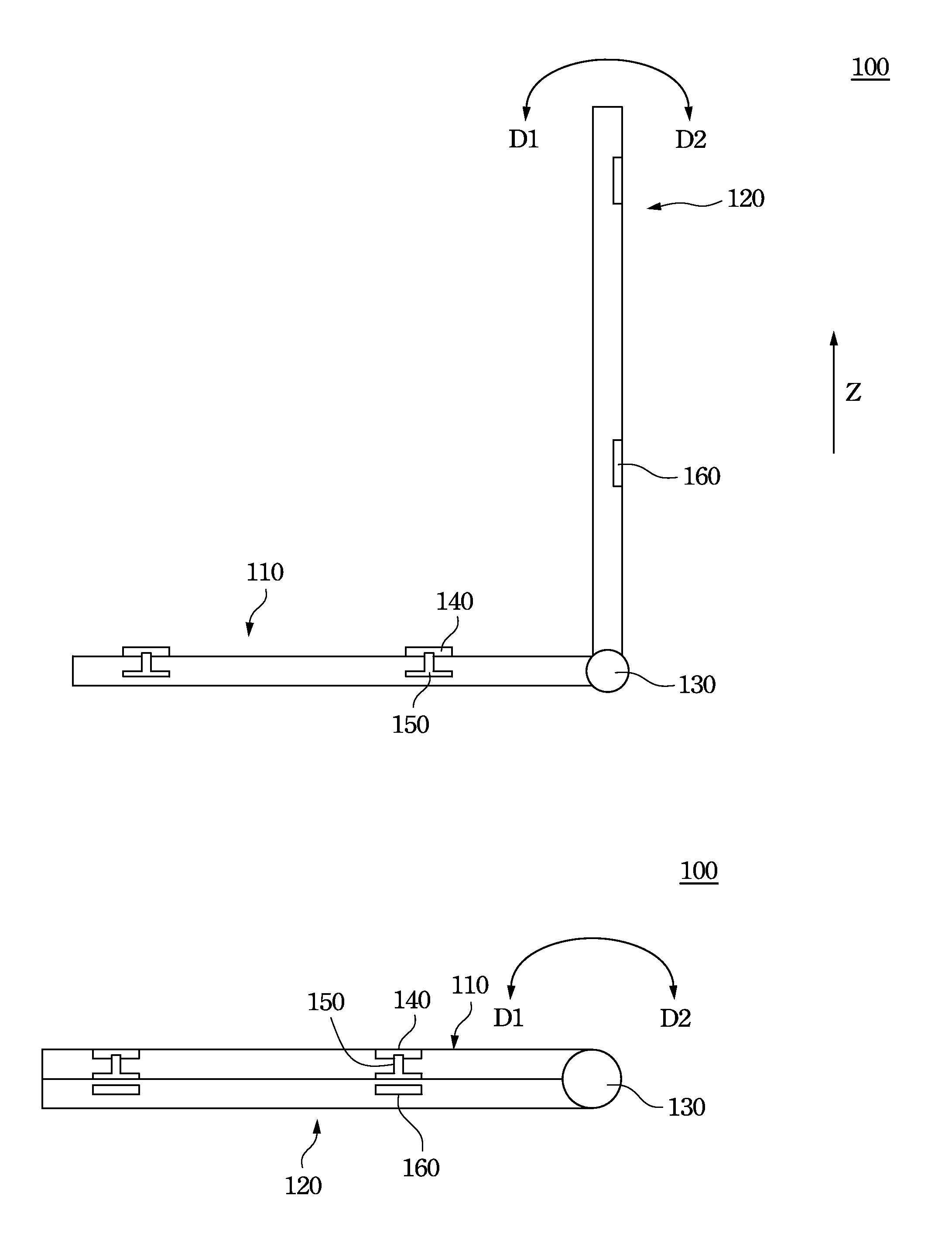
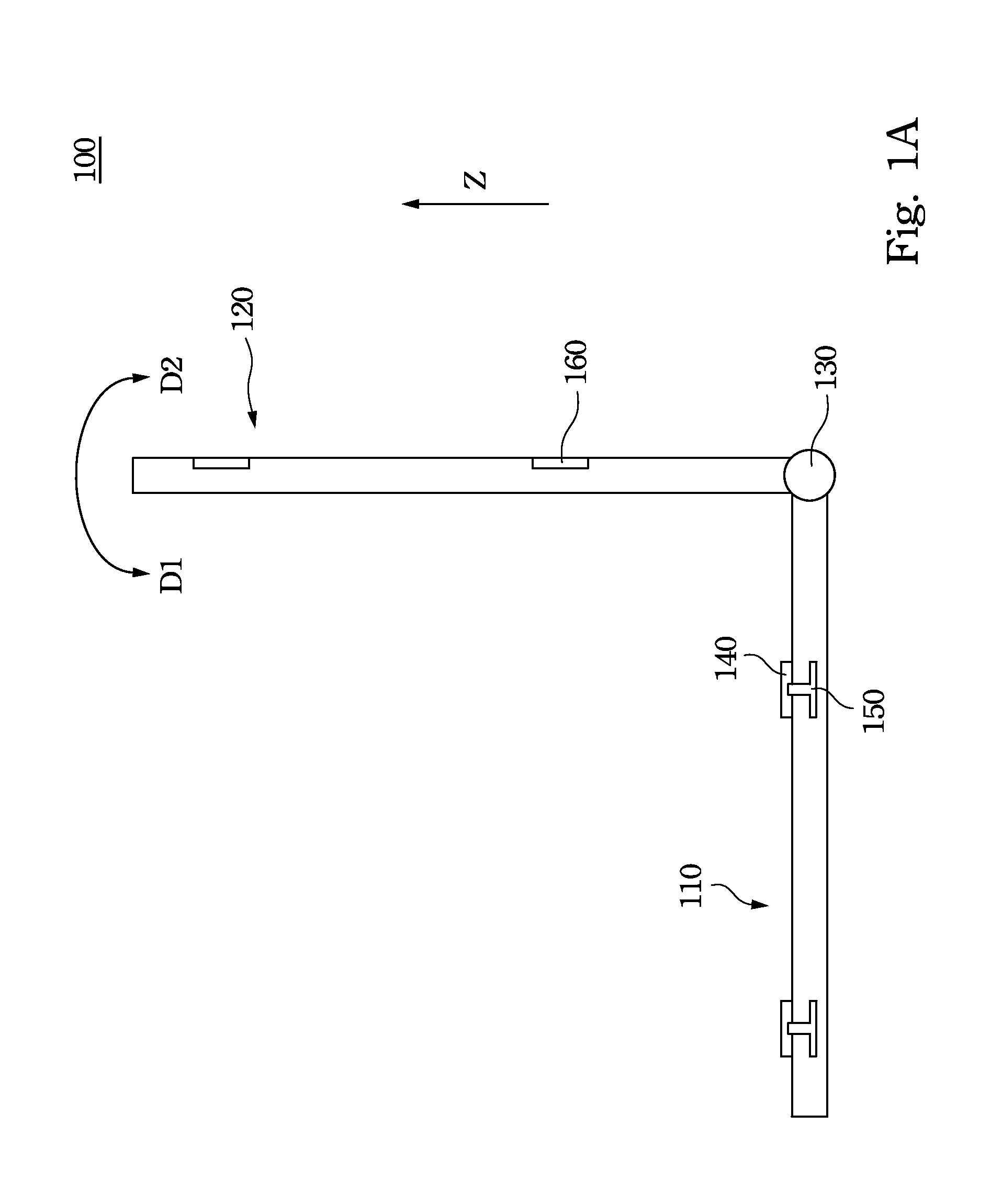
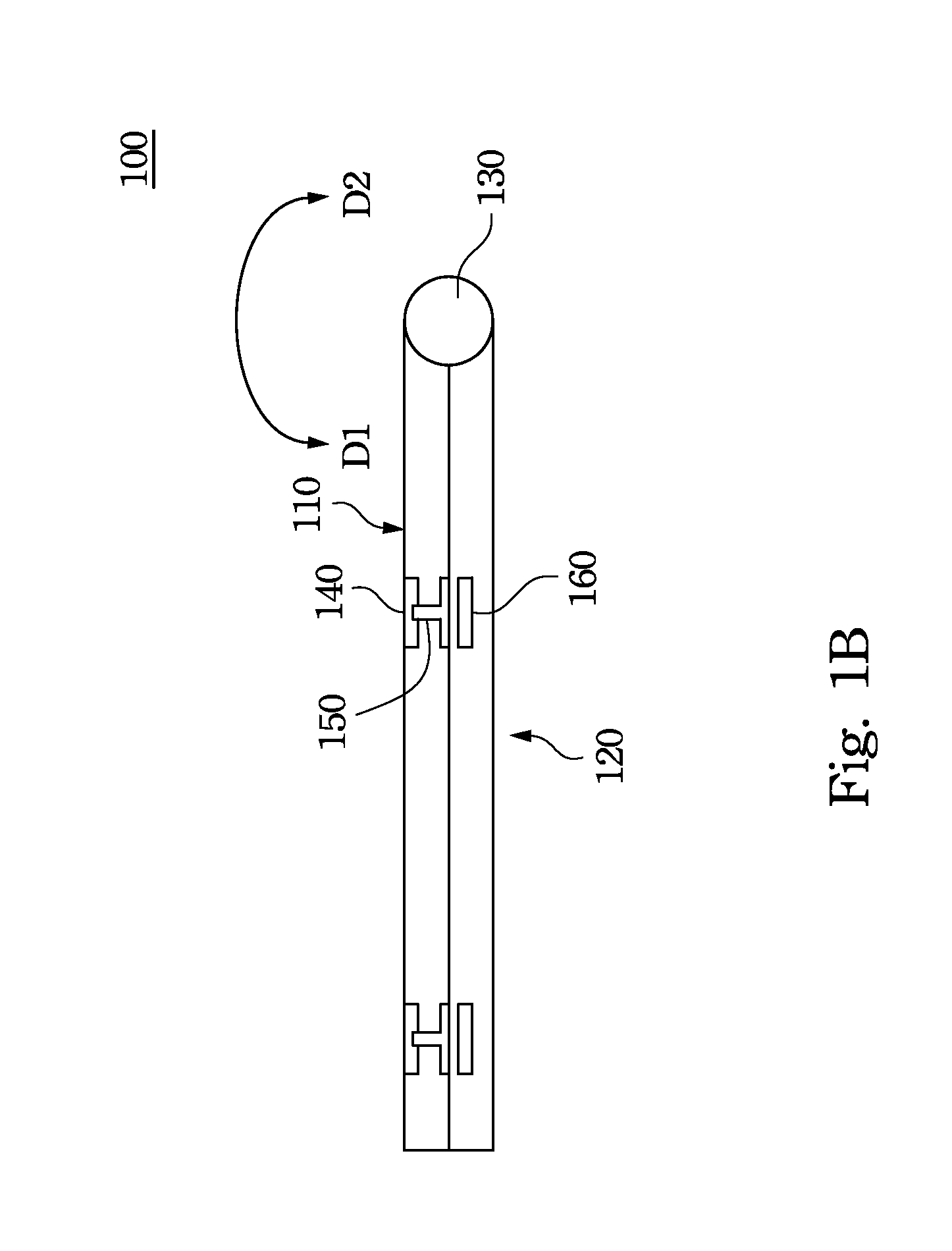
[0057]According to the present invention, the foldable electric device 600 comprises a first member 610, a second member 620 and a pivot portion 630. The pivot portion 630 is used to pivot the first member 610 and the second member 620. As such, the second member 620 can be pivotally rotated to cover on the first member 610, or the second member 620 can be pivotally rotated to leave away from the first member 610 (as sown in FIG. 7A). Substantially, the second member 620 can pivotally rotate in a counterclockwise direction (D1) for forwardly covering on a top surface of the first member 610 (not shown in figures), or the second member 620 can pivotally rotate in a clockwise direction (D2) for reversely covering on the bottom surface of the first member 610 (as shown in FIG. 7B).

[0058]The first member 610 at least has an operation interface 615 (e.g. a keyboard or touch panel), a cushion pad 611, a first magnetic component 612 and an elastic member 613. The operation interface 615 is...


PUM


Abstract

A foldable electric device comprises a first member, a second member and a pivot portion. The pivot portion is used to pivot the first member and the second member. The first member comprises a first cushion pad and a first magnetic component. The first cushion pad is retractably disposed on a surface of the first member. The first magnetic component is installed in the first member, and synchronously moves with the first cushion pad. The second member comprises a second magnetic component. When the first member and the second member are covered together, with the magnetic effect between the first magnetic component and the second magnetic component, the first cushion pad is linked by the first magnetic unit to protrude from or retract into the first member.

Description

RELATED APPLICATIONS[0001]This application claims priority to Taiwanese Application Serial Number 100212954, filed Jul. 14, 2011, which is herein incorporated by reference.BACKGROUND[0002]1. Technical Field[0003]The present invention relates to a portable computer, more particular to a portable computer having movable cushion pads.[0004]2. Description of Related Art[0005]The portable computer, e.g. a notebook computer, is one of the most popular products in the electronic device market. Because the development of notebook computer is getting matured, a consumer now pays more attention on the appearance design or the convenience in use, instead of the calculation capability of the computer itself, when the user would like to choose a portable computer.[0006]The top chassis and the bottom chassis of a notebook computer are pivotally connected with each other, and the top chassis and the bottom chassis can be rotated to cover one another. The bottom chassis has a keyboard surface and a...

Claims


Application Information

Patent Timeline
IPC IPC(8): H05K5/00
CPCG06F1/1679G06F1/1675G06F1/1618
Inventor YEH, SHU-HUACHEN, CHI-FUTSENG, FANG-HSIANGLIN, CHUN-CHENG
Owner QUANTA COMPUTER INC
Why Eureka
Try Eureka