Feed auger with paddles

a technology of augers and paddles, applied in the field of electrographic processing, can solve the problems of development mass and image density, and reduce the development of images and density

Inactive Publication Date: 2013-01-24
EASTMAN KODAK CO
View PDF6 Cites 3 Cited by
  • Summary
  • Abstract
  • Description
  • Claims
  • Application Information

AI Technical Summary

Problems solved by technology

As the toner concentration decreases, the developed mass and image density also decrease undesirably.
However, the volume of developer in the first channel does not remain constant down its length, usually resulting in more developer on the development roller near the first end of the feed auger, where there is a relatively large volume of developer in the first channel.

Method used


Image

  • Feed auger with paddles
  • Feed auger with paddles
  • Feed auger with paddles

Examples


Embodiment Construction

[0018]The present invention will be directed in particular to elements forming part of, or in cooperation more directly with the apparatus in accordance with the present invention. It is to be understood that elements not specifically shown or described may take various forms well known to those skilled in the art.

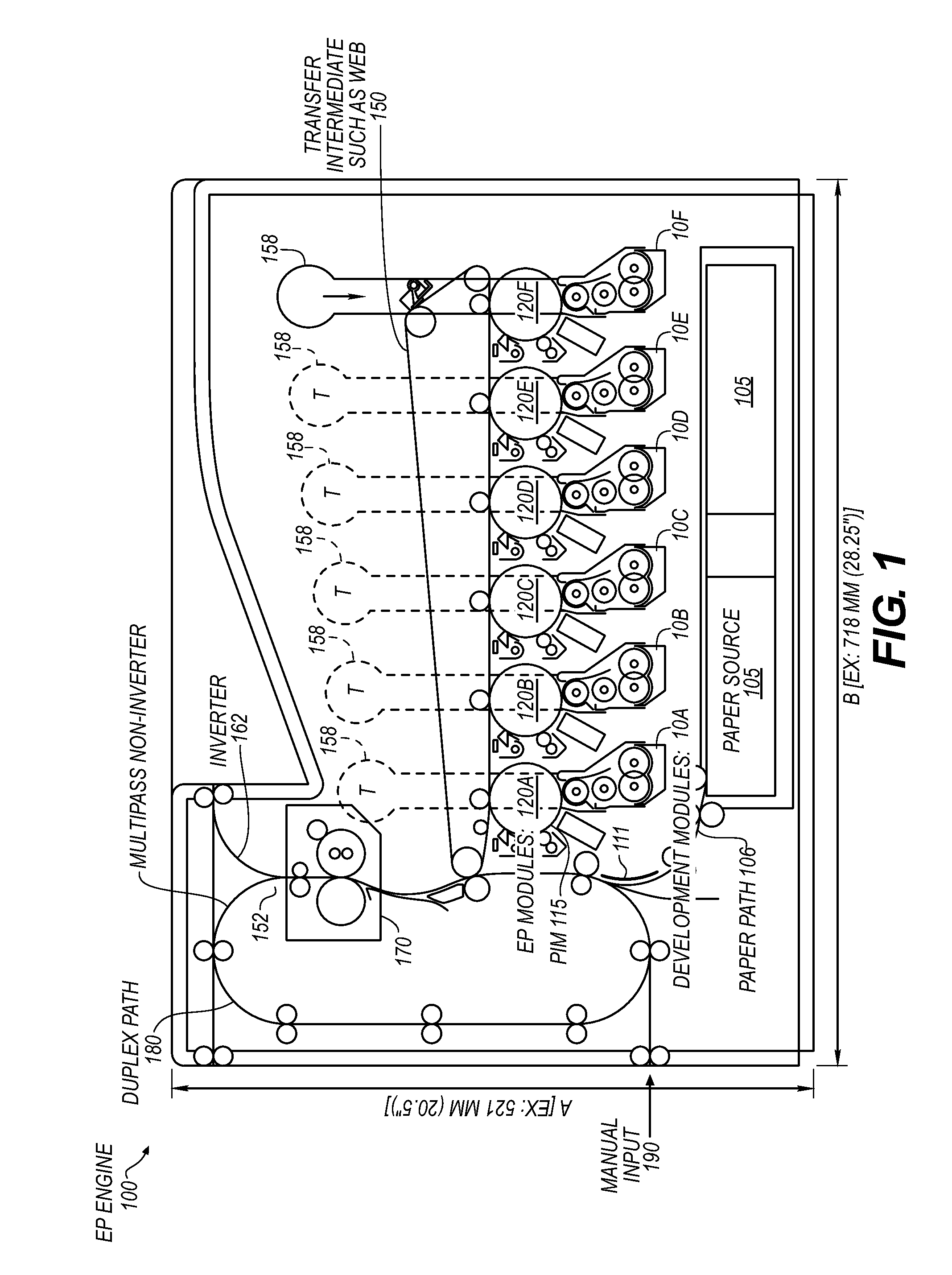
[0019]FIG. 1 shows an electrophotographic (EP) engine 100 or printer, often referred to as a tandem print engine including EP modules (120A, 120B, 120C, 120D, 120E, and 120F), wherein each contains a single primary imaging member 115 and a single development system (10A, 10B, 10C, 10D, 10E, and 10F) to print on receiver 111. The EP printer is shown having dimensions of A×B which are around in one example, 521×718 mm or less. Development stations 10A-10D would typically contain marking particles that are used in most color prints. For example, marking particles of the subtractive primary colors cyan, magenta, yellow, and black would be contained in four of these development...


PUM


Abstract

A development system (10) for an electrophotographic printer with multiple augers containing a development roller (11) and a first channel contains a feed auger (13) and developer, with a plurality of paddles (12) attached to the feed auger, at least some the paddles increase in size with respect to a previous paddle along a direction of developer flow (18). This arrangement of paddles ensures that a uniform layer of developer is formed on the development roller despite the volume of developer in the first channel decreasing along the length of the first channel in the direction of developer flow.

Description

CROSS REFERENCE TO RELATED APPLICATIONS[0001]Reference is made to commonly-assigned copending U.S. patent application Ser. No. ______ (Attorney Docket No. 96491 / NAB), filed herewith, entitled METHOD OF USING FEED AUGER WITH PADDLES, by Bucks et al.; the disclosure of which is incorporated herein.FIELD OF THE INVENTION[0002]The present invention relates to electrostatography, including electrography and electrophotography, and more particularly, to the design of a development system with multiple augers for an electrophotographic printer.BACKGROUND OF THE INVENTION[0003]The three channel development system used in electrophotographic printers has a development roller that moves developer containing toner into proximity with a primary imaging member, usually a photoconductor; and a first channel containing a feed auger, a second channel containing a second auger, a third channel containing at least a third auger, and possibly a fourth auger. The primary imaging member is used for form...

Claims


Application Information

Patent Timeline
Patent Type & Authority Applications(United States)
IPC IPC(8): G03G15/08
CPCG03G15/0893G03G2215/0819G03G2215/0838G03G2215/0827G03G2215/0822
Inventor BUCKS, RODNEY R.LIVADAS, JERRY E.STELTER, ERIC C.
Owner EASTMAN KODAK CO
Why Eureka
Try Eureka