
Toner supply device and image forming apparatus

a technology of toner supply device and image forming apparatus, which is applied in the direction of electrographic process apparatus, instruments, optics, etc., can solve the problems of scraping member heavy load, toner becoming deteriorated, and the majority of unused toner remains in the toner container, so as to achieve less deterioration of toner

Active Publication Date: 2013-01-24
SHARP KK
View PDF4 Cites 0 Cited by
  • Summary
  • Abstract
  • Description
  • Claims
  • Application Information

AI Technical Summary

Benefits of technology

The technology described in this patent aims to reduce the amount of unused toner in a toner container while minimizing the strain on the toner. The toner container rotates around an axis when joined to a rotary drive source outside the container, and a scraping member inside the container rotates with the toner. The scraping member contains a curved section that follows the spiral of the toner container and helps to scrape off toner adhering to the walls. This results in a higher fluidity of the toner, making it easier to discharge from the container. The scraping member is designed to rotate freely and can easily scrape off toner adhering to the walls, reducing the amount of unused toner and improving the image quality.

Problems solved by technology

As a result, most of an unused toner remains in the toner container in some cases.
Therefore, when there is a small amount of toner in the toner container, it is possible to scrape off the toner with the scraping member for certain, however, when there is a large amount of toner remaining in the toner container, a load on the toner caused by the scraping member is large, so that the toner becomes deteriorated, which poses a problem.
Moreover, there is a possibility that as counteraction to the load on the toner, a heavy load is also imposed on the scraping member so that the scraping member is broken.

Method used


Image

  • Toner supply device and image forming apparatus
  • Toner supply device and image forming apparatus
  • Toner supply device and image forming apparatus

Examples


Embodiment Construction

[0039]Now referring to the drawings, preferred embodiments are described below.

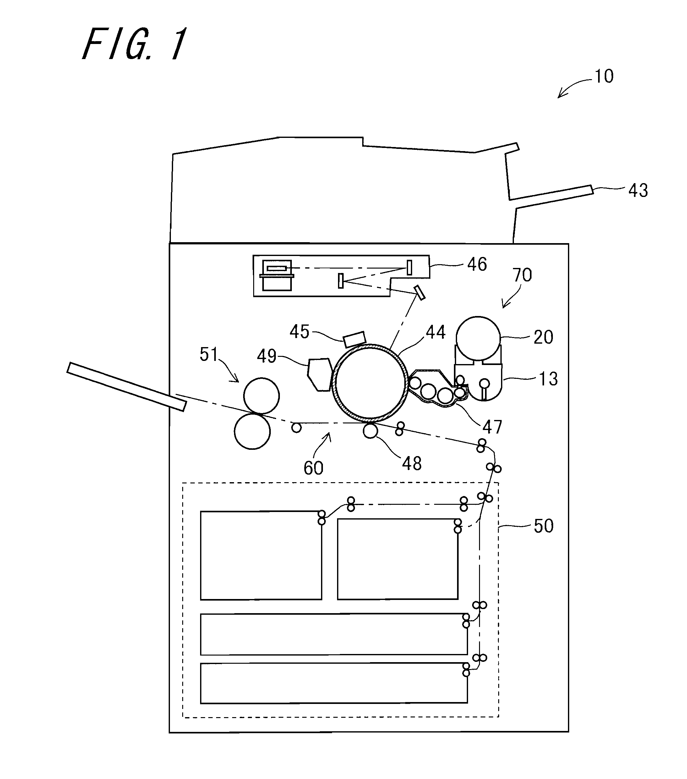
[0040]First, description will be given for an image forming apparatus 10 including a toner supply device 20 according to an embodiment. FIG. 1 is a schematic view showing a configuration of the image forming apparatus 10. The image forming apparatus 10 is an apparatus which forms an image on a surface of a recording medium such as a recording sheet by electrophotography to obtain a printed matter. The image forming apparatus 10 includes a recording medium supply section 50 which supplies a recording medium, a scanner 43 which reads image information from a document or the like, and an electrophotographic process section 60 which forms an image on a supplied recording medium based on the image information read by the scanner or image information inputted from an apparatus which is external to the image forming apparatus 10. The electrophotographic process section 60 includes a photoreceptor drum 44, a char...


PUM


Abstract

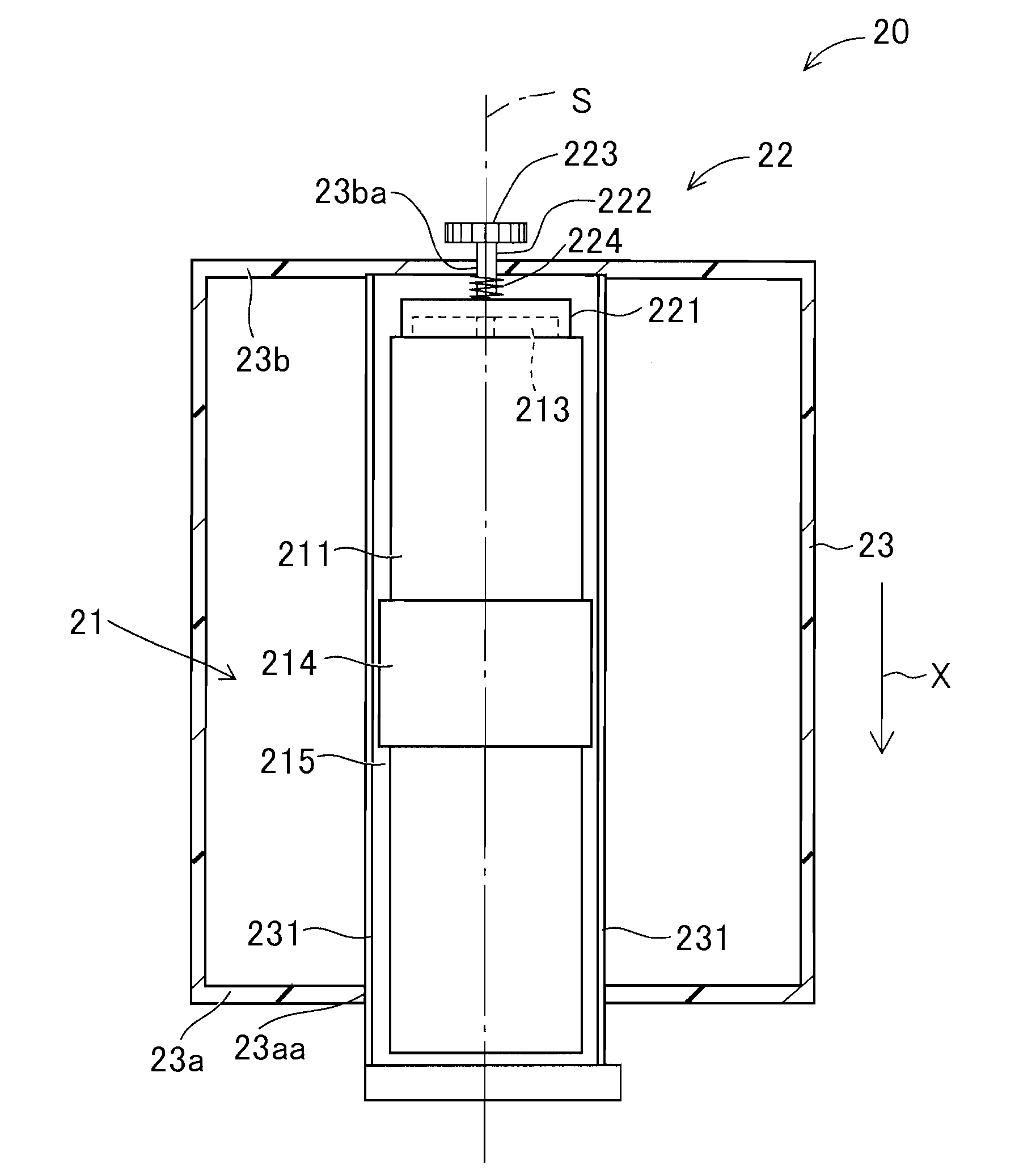
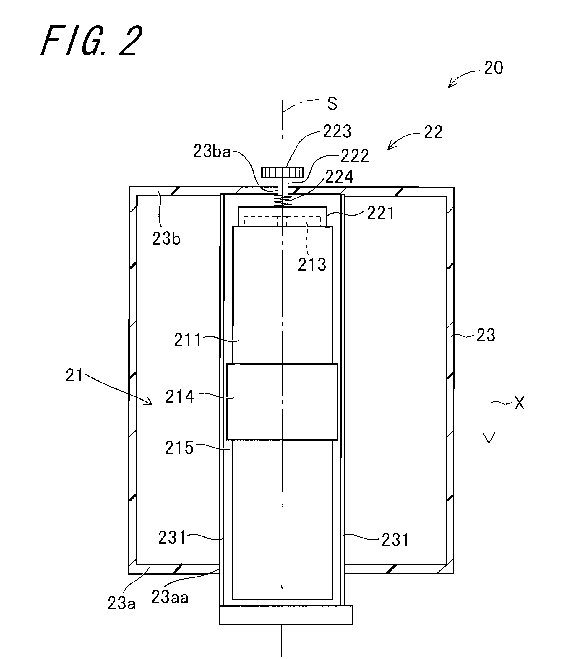
A rotary-type toner supply device includes a toner container and a scraping member. The toner container has a peripheral wall section which is shaped so as to surround a side face of an imaginary column K1 along the side face and has a toner discharge port formed therein, and contains toner in space surrounded by the peripheral wall. The scraping member is contained in the space so as to freely rotate around a central axis S of the imaginary column K1, and has first and second curved parts, each of the first and second curved parts extending along a portion of a half cycle or more of a spiral on the side face of the imaginary column K1.

Description

CROSS-REFERENCE TO RELATED APPLICATION[0001]This application claims priority to Japanese Patent Application No. 2011-160370, which was filed on Jul. 21, 2011, the contents of which are incorporated herein by reference in its entirety.BACKGROUND OF THE TECHNOLOGY[0002]1. Field of the Technology[0003]The present technology relates to a toner supply device and an image forming apparatus.[0004]2. Description of the Related Art[0005]An image forming apparatus equipped with a printer, a multifunction peripheral and the like forms an image using toner reserved in a developing device included in the image forming apparatus. There has been known a toner supply device which supplies toner to the developing device in a field of such an image forming apparatus. When toner in the developing device is consumed and reduced, the toner supply device supplies toner in a toner container included in the toner supply device to a toner hopper connected to the developing device, and the toner hopper suppl...

Claims


Application Information

Patent Timeline
IPC IPC(8): G03G15/08
CPCG03G2215/0665G03G2215/0675G03G2215/0685G03G2215/0816G03G15/0872G03G15/0836G03G15/087G03G2215/0663G03G2215/085
Inventor ICHIKAWA, YOSHIKI
Owner SHARP KK
Learn More