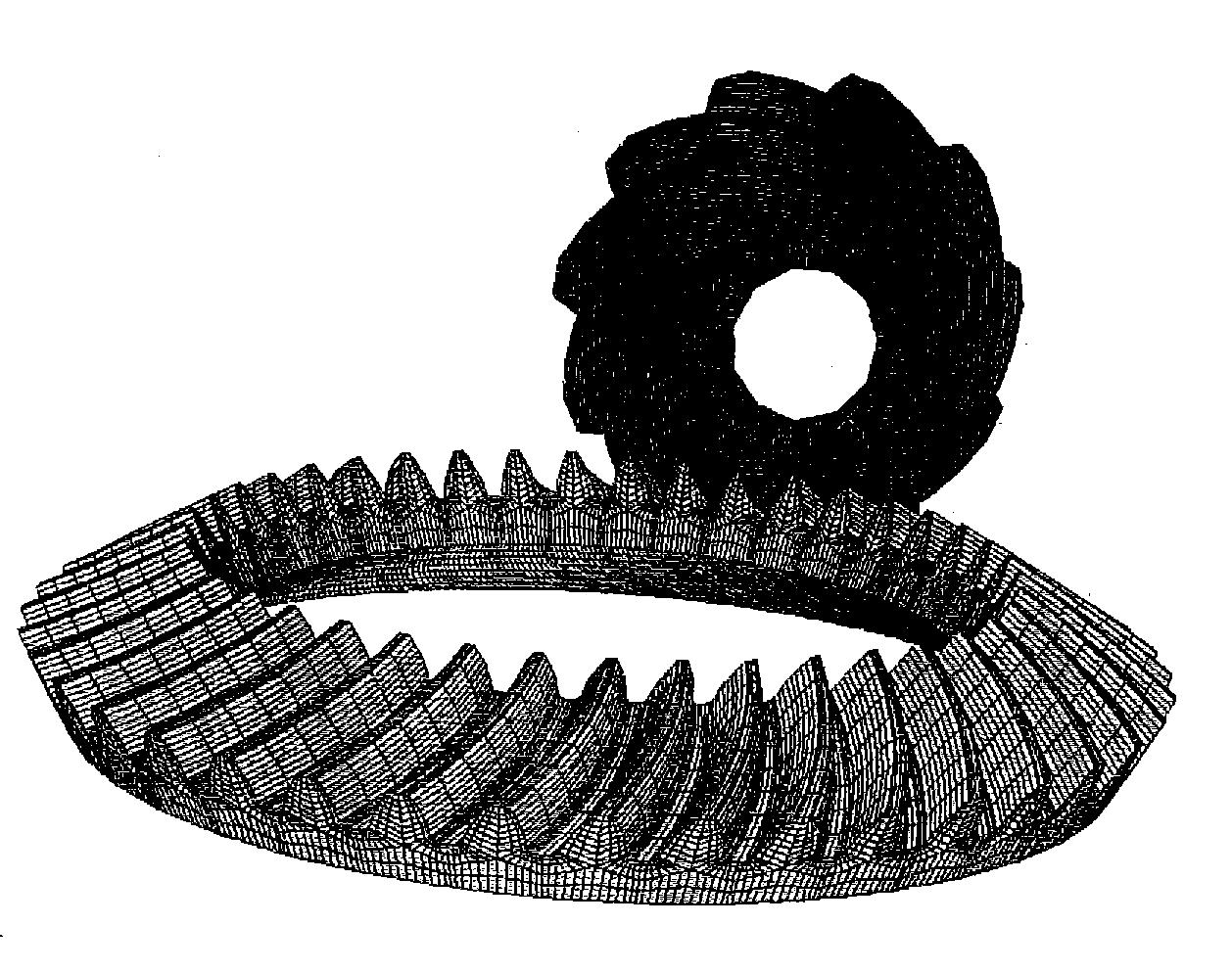
Optimization of face cone element for spiral bevel and hypoid gears

a technology of spiral bevels and cone elements, applied in the direction of gear teeth, other domestic articles, etc., can solve the problems of reduced working area of tooth surfaces, unfavorable sex and sex, and uneven tooth root tip clearance, so as to avoid root tip interference, maximize contact ratio, and optimize tooth root tip clearance

Inactive Publication Date: 2013-01-31
GLEASON WORKS
View PDF24 Cites 22 Cited by
  • Summary
  • Abstract
  • Description
  • Claims
  • Application Information

AI Technical Summary

Benefits of technology

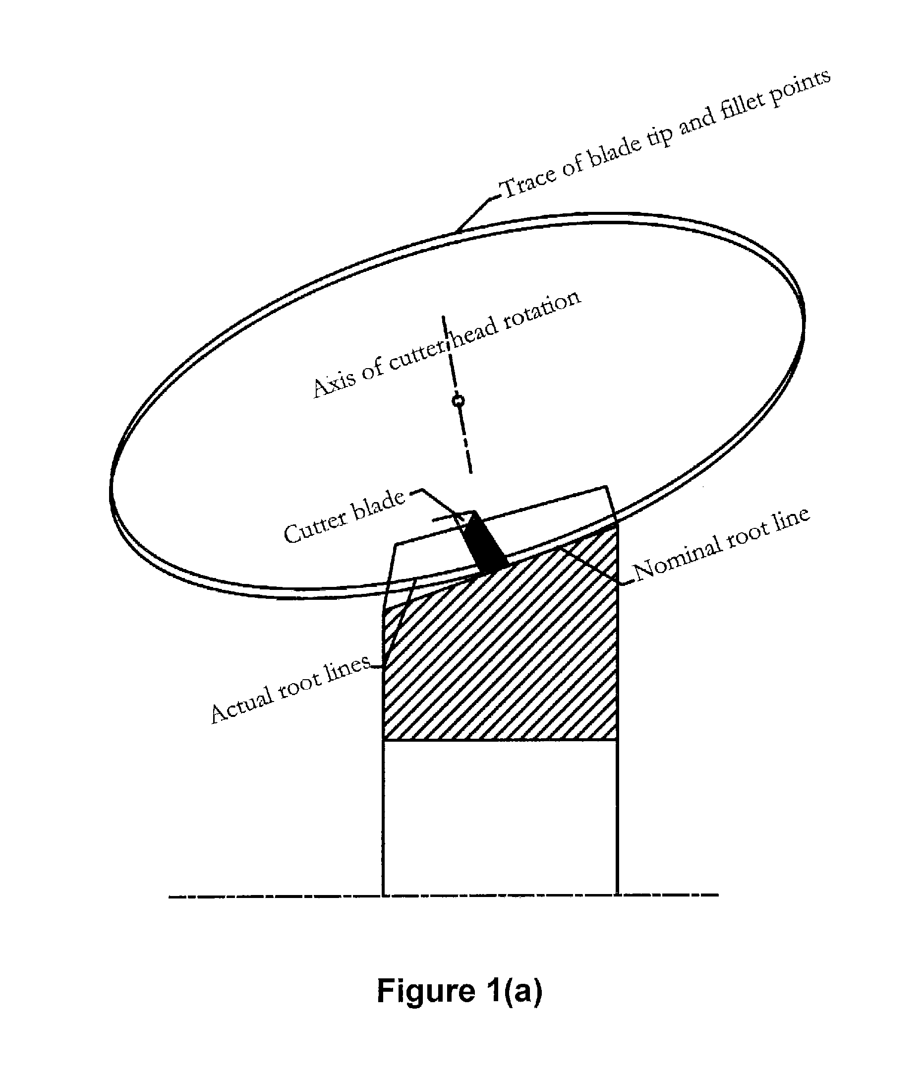
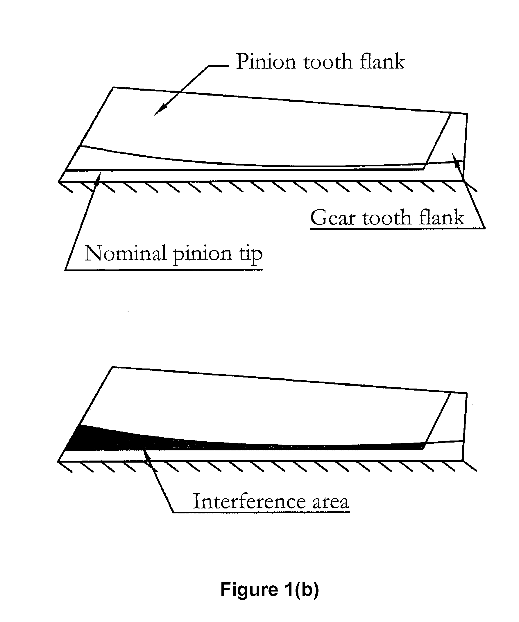
[0028]The present invention is directed to a method of determining an optimized face cone element for spiral bevel and hypoid gears. The form of the root fillet of one member of a gear pair is determined and that form is transferred to the tip of the other member of the gear pair. With the inventive method, tooth root-tip clearance is optimized and the contact ratio is maximized, while avoiding root-tip interference between mating gear members.
[0029]The inventive method comprises producing a gear blank having an outer surface wherein a gear manufactured from the gear blank will have tooth tips that do not interfere with tooth root fillets of a mating gear when the gear and the mating gear are run in mesh. The method includes the steps of defining tooth surfaces of each of the gear and the mating gear and defining the form of a root fillet line o

Problems solved by technology

As a result, the tooth top geometry may not fit the mating member's real root shape, providing an uneven tooth root-tip clearance.
To avoid the root-tip inte

Method used


Image

  • Optimization of face cone element for spiral bevel and hypoid gears
  • Optimization of face cone element for spiral bevel and hypoid gears
  • Optimization of face cone element for spiral bevel and hypoid gears

Examples


Embodiment Construction

[0044]Before any features and at least one construction of the invention are explained in detail, it is to be understood that the invention is not limited in its application to the details of construction and the arrangements of the components set forth in the following description or illustrated in the drawings. The invention is capable of other constructions and of being practiced or being carried out in various ways. Also, it is understood that the phraseology and terminology used herein is for the purposes of description and should not be regarded as limiting.

[0045]The terms “invention,”“the invention,” and “the present invention” used in this specification are intended to refer broadly to all of the subject matter of this specification and the patent claims below. Statements containing these terms should not be understood to limit the subject matter described herein or to limit the meaning or scope of any patent claim below. Furthermore, this specification does not seek to desc...


PUM

PropertyMeasurementUnit
Interferenceaaaaaaaaaa
Radiusaaaaaaaaaa

Abstract

A method of determining an optimized face cone element for spiral bevel and hypoid gears. The form of the root fillet of one member of a gear pair is determined and that from is transferred to the tip of the other member of the gear pair. With the inventive method, tooth root-tip clearance is optimized and the contact ratio is maximized while avoiding root-tip interference between mating gear members.

Description

[0001]This application claims the benefit of U.S. Provisional Patent Application No. 61 / 512,986 filed Jul. 29, 2011 the entire disclosure of which is hereby incorporated by reference.FIELD OF THE INVENTION[0002]The present invention is directed to spiral bevel and hypoid gears and in particular, to the optimization of the face cone element of spiral bevel and hypoid gears.BACKGROUND OF THE INVENTION[0003]In the production of gears, especially bevel gears, two types of processes are commonly employed, generating processes and non-generating processes.[0004]Generating processes can be divided into two categories, face milling (intermittent indexing) and face hobbing (continuous indexing). In generating face milling processes, a rotating tool is fed into the workpiece to a predetermined depth. Once this depth is reached, the tool and workpiece are then rolled together in a predetermined relative rolling motion, known as the generating roll, as though the workpiece were rotating in mesh...

Claims


Application Information

Patent Timeline
IPC IPC(8): F16H1/14B23F15/00B23P15/14
CPCF16H55/088B23F17/001B23F17/005Y10T409/10Y10T74/19665Y10T29/49478B23F19/002Y10T74/19949Y10T74/19958Y10T409/103975Y10T409/104293
Inventor FAN, QI
Owner GLEASON WORKS
Why Eureka
Try Eureka