Screen Printing Device with Infinite Loop Stencil

a stencil and printing device technology, applied in printing, coatings, printed circuit manufacturing, etc., can solve the problems of frequent stoppage of fabrication process, time-consuming process, and large amount of solder pas

Inactive Publication Date: 2013-01-31
MONCAVAGE CHARLES
View PDF9 Cites 9 Cited by
  • Summary
  • Abstract
  • Description
  • Claims
  • Application Information

AI Technical Summary

Problems solved by technology

This can be a time intensive process with the constant starting and stopping of the conveyor.
Additionally, solder paste tends to build up in the stencil openings, which requires the fabrication process to be frequently stopped in order to clean the stencil.
An additional problem with the current process is that, after the solder paste is applied, as the stencil is being lifted from the substrate, solder paste may also be lifted from the substrate, resulting in a less than desired application of the solder paste on the substrate.

Method used


Image

  • Screen Printing Device with Infinite Loop Stencil
  • Screen Printing Device with Infinite Loop Stencil
  • Screen Printing Device with Infinite Loop Stencil

Examples


Embodiment Construction

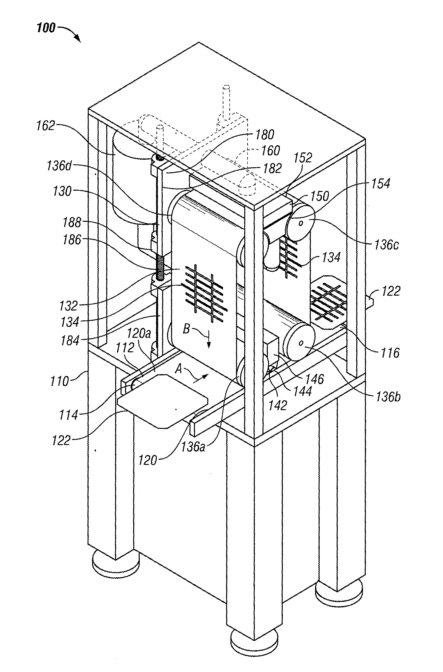
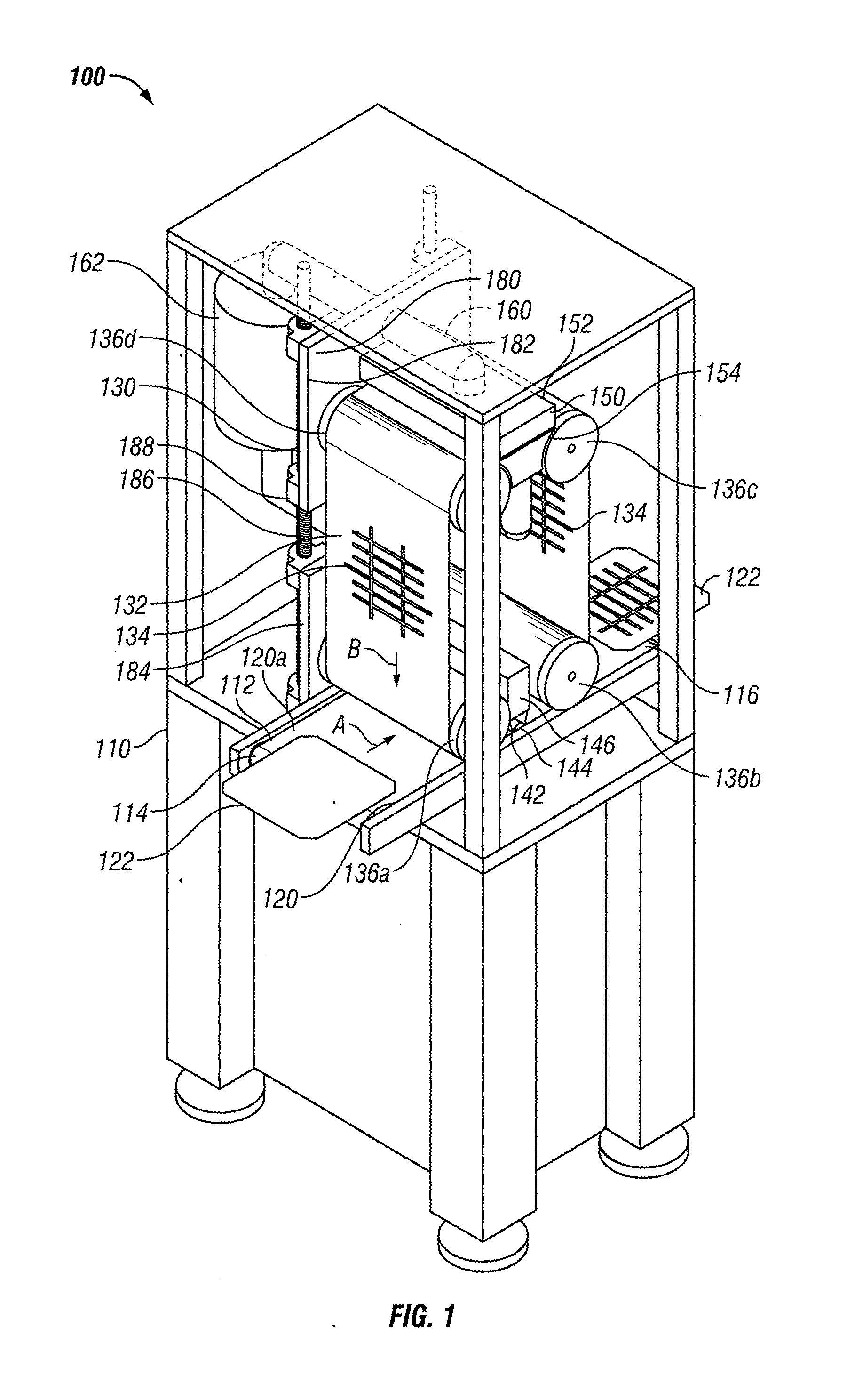
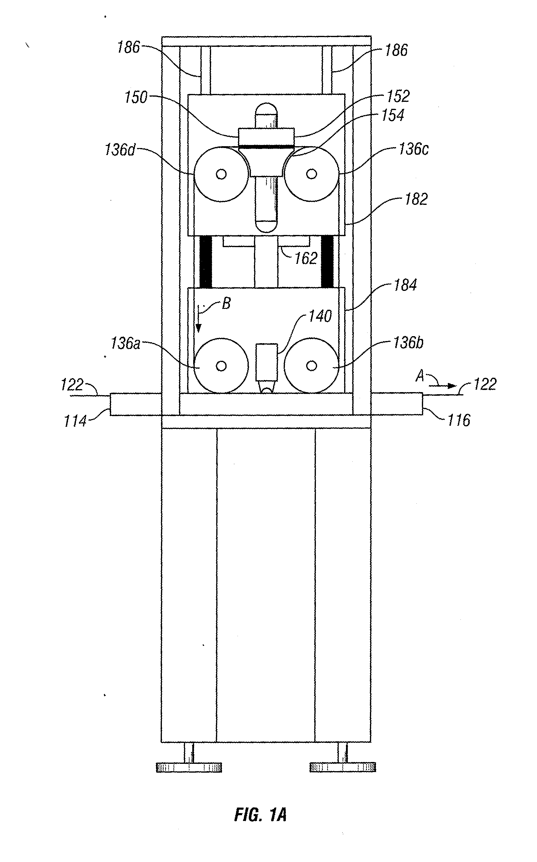
[0024]Certain terminology is used in the following description for convenience only and is not limiting. The terminology includes the words above specifically mentioned, derivatives thereof and words of similar import. As used herein, the terms “upstream” and “downstream” are used to identify relative locations and directions of elements used in the present invention. A first device is upstream of a second device when the direction of movement results in the first device being encountered before the second device. Similarly, a first device is downstream of a second device when the direction of movement results in the first device being encountered after the second device. Further, as used herein, the term “roller” can mean a cylindrical device, a tubular device, a wheel, or any other rotatable device having a generally circular or curved outer perimeter around which an endless loop stencil may be rolled.

[0025]The embodiments described and illustrated below are not intended to be exh...


PUM


Abstract

A screen printing device is disclosed. The screen printing device includes a screen printer workstation having a work path. The work path has an input end, an output end, and a conveyor for transporting a workpiece between the input end and the output end. A stencil assembly is adapted to engage the workpiece as the workpiece is transported between the input end and the output end. The stencil assembly includes a stencil having an endless loop. A method of applying a substance to a workpiece using an endless loop stencil is also disclosed.

Description

FIELD OF THE INVENTION[0001]The present invention relates to a screen printing device for manufacturing electronic printed circuit boards that uses an infinite loop stencil to apply solder paste to a substrate.BACKGROUND OF THE INVENTION[0002]Screen printing machines are used during the fabrication of printed circuit boards. Planar substrates are advanced from a conveyor through the machine sequentially in a start-stop sequence during which, when the substrate stopped at a print location, a stencil is laid over the substrate and solder paste is spread over the stencil, with the solder paste being forced through openings in the stencil and onto the substrate. This can be a time intensive process with the constant starting and stopping of the conveyor.[0003]Additionally, solder paste tends to build up in the stencil openings, which requires the fabrication process to be frequently stopped in order to clean the stencil. An additional problem with the current process is that, after the ...

Claims


Application Information

Patent Timeline
Patent Type & Authority Applications(United States)
IPC IPC(8): B05C17/08
CPCH05K3/1225B05C17/08H05K2203/1545H05K3/3484B41F35/003B41F15/0809B41F15/0881H05K3/3485
Inventor MONCAVAGE, CHARLES
Owner MONCAVAGE CHARLES
Why Eureka
Try Eureka