Easily Implantable And Stable Nail-Fastener For Skeletal Fixation And Method

a stable and easy-to-implement technology, applied in the field of easy-to-implement and stable nail-fastener for skeletal fixation and method, can solve problems such as independency

Inactive Publication Date: 2013-01-31
KETTERING UNIVERSITY
View PDF2 Cites 12 Cited by
  • Summary
  • Abstract
  • Description
  • Claims
  • Application Information

AI Technical Summary

Benefits of technology

[0010]Another aspect of the invention provides a method for implanting the intramedullary nail into the medullary canal surrounded by the cortex of the bone. The method includes providing the bore in the intramedullary nail including threads, forming the near cortex hole in the cortex, providing the threaded fastener including the head and the end with the compression portion presenting the compression portion diameter and the threaded portion extending along the fastener axis between the head and the end. The method also includes providing the compression transmission device having the exterior and the interior defining the interior space, disposing the compression transmission device in the near cortex hole and contacting the intramedullary nail with the compression transmission device, extending the threaded fastener through the compression transmission device, and threadedly engaging the threaded portion of the threaded faster to the intramedullary nail along the bore. The method further includes providing the compression transmission device with the interior space being greater than the compression portion diameter of the threaded fastener for providing space at least partially about the threaded fastener for allowing the fastener axis to be variously disposed relative the interior space.

Problems solved by technology

Additionally, there is interdigitation of the male and female parts, thus, they are not independent of one another.

Method used


Image

  • Easily Implantable And Stable Nail-Fastener For Skeletal Fixation And Method
  • Easily Implantable And Stable Nail-Fastener For Skeletal Fixation And Method
  • Easily Implantable And Stable Nail-Fastener For Skeletal Fixation And Method

Examples


Embodiment Construction

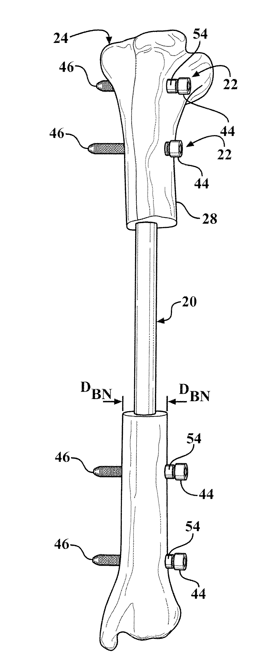
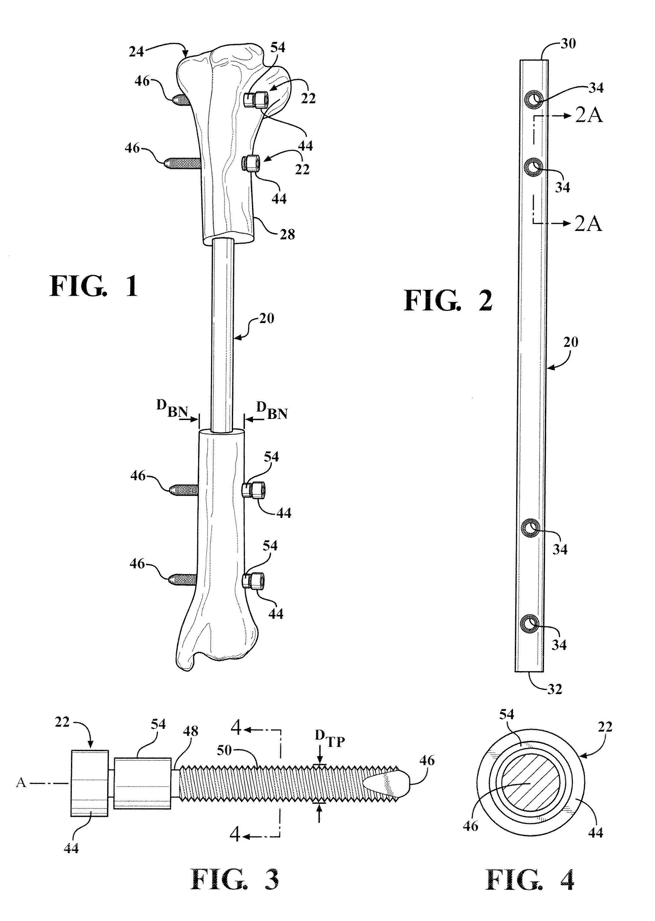
[0050]Referring to the Figures, wherein like numerals indicate corresponding parts throughout the several views, an intramedullary nail 20 and fastener 22 for skeletal fixation constructed in accordance with the subject invention is shown in FIGS. 1-26.

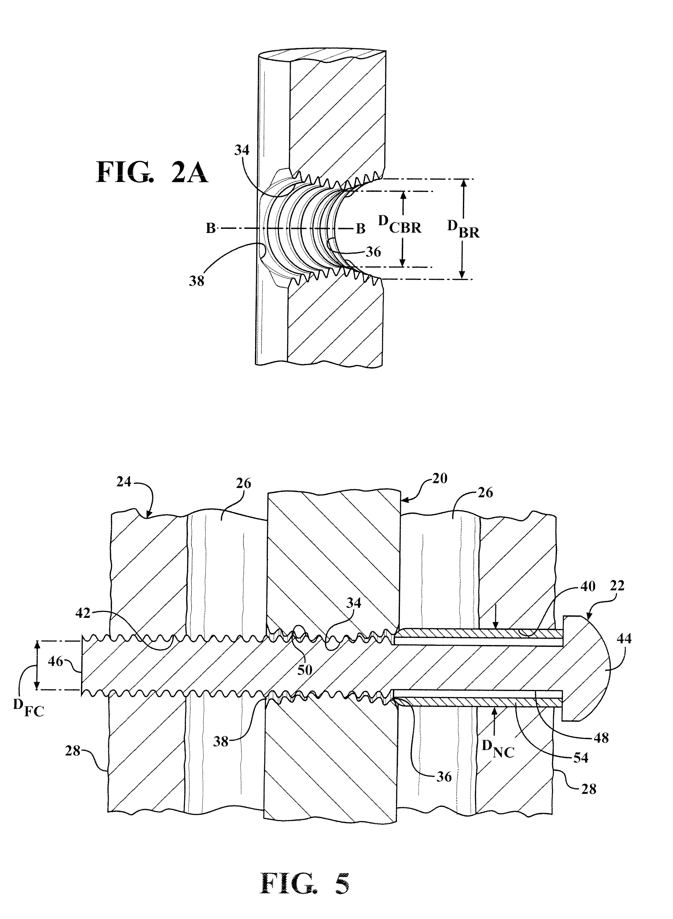
[0051]The nail-fastener apparatus includes the intramedullary nail 20 for insertion into a bone 24 having a bone diameter DBN and including a medullary canal 26 surrounded by a cortex 28. The intramedullary nail 20, generally indicated, extends longitudinally in the medullary canal 26 of the bone 24 along a nail axis An between a top end 30 and a bottom end 32 thereof. The intramedullary nail 20 can be solid between the top end and the bottom end 32, as shown in FIGS. 5, 6, and 16. Alternatively, the intramedullary nail 20 can present a hollow opening 21 between the top end and the bottom end 32, as shown in FIGS. 17-17b. The intramedullary nail 20 also defines a bore 34 disposed transverse to, i.e., extending across but is not necess...


PUM


Abstract

An intramedullary nail (20) defining a bore (34) is inserted into a medullary canal (26) of a bone (24). A threaded fastener (22) has a compression portion (48) presenting a compression portion diameter (DCP) and a threaded portion (50) presenting a threaded portion diameter (DTP). The fastener (22) extends through a near cortex hole (40) and / or a far cortex hole (42), and the threaded portion (22) threadedly engages the bore (34). A compression transmission device (54) is disposed between a head (44) of the fastener (22) and the intramedullary nail (20) for transmitting the compressional load of the threaded fastener (22) to the intramedullary nail (20). An interior space of the compression transmission device (54) is greater than the compression portion diameter (DCP) providing space about the threaded fastener (22) for allowing the fastener axis (A) to be variously disposed relative to the interior space.

Description

CROSS REFERENCE TO RELATED APPLICATION[0001]This application is a continuation-in-part of U.S. patent application Ser. No. 12 / 818,395, filed Jun. 18, 2010, the entire contents of which is hereby incorporated by reference.STATEMENT REGARDING FEDERALLY SPONSORED RESEARCH[0002]This invention was made with Government support under contract numbers W81XWH0720119 and W81XWH1120128 awarded by the United States Army Medical Research Acquisition Activity. The Government has certain rights in this invention.BACKGROUND OF THE INVENTION[0003]1. Field of the Invention[0004]An easily implantable and stable nail-fastener for skeletal fixation to treat bone fractures and to provide support to the long bones and a method for implanting the nail-fastener.[0005]2. Related Art[0006]An intramedullary nail for skeletal fixation of the type to which the subject invention pertains includes a threaded fastener extending through a compression transmission device to threadedly engage the nail. The compression...

Claims


Application Information

Patent Timeline
Patent Type & Authority Applications(United States)
IPC IPC(8): A61B17/72
CPCA61B17/725A61B17/686
Inventor LECRONIER, DAVIDATKINSON, PATRICK
Owner KETTERING UNIVERSITY
Why Eureka
Try Eureka