
Self-Locking Fastener

a self-locking and fastener technology, applied in the direction of snap fasteners, buckles, transportation and packaging, etc., can solve the problems of economic inability, poor product image, and welding machine to weld two pieces together, so as to enhance the connection of the buckle base, facilitate and facilitate use and operation, the effect of reducing the packing cos

Inactive Publication Date: 2013-02-07
DONGGUAN MASTER INK CO LTD
View PDF13 Cites 37 Cited by
  • Summary
  • Abstract
  • Description
  • Claims
  • Application Information

AI Technical Summary

Benefits of technology

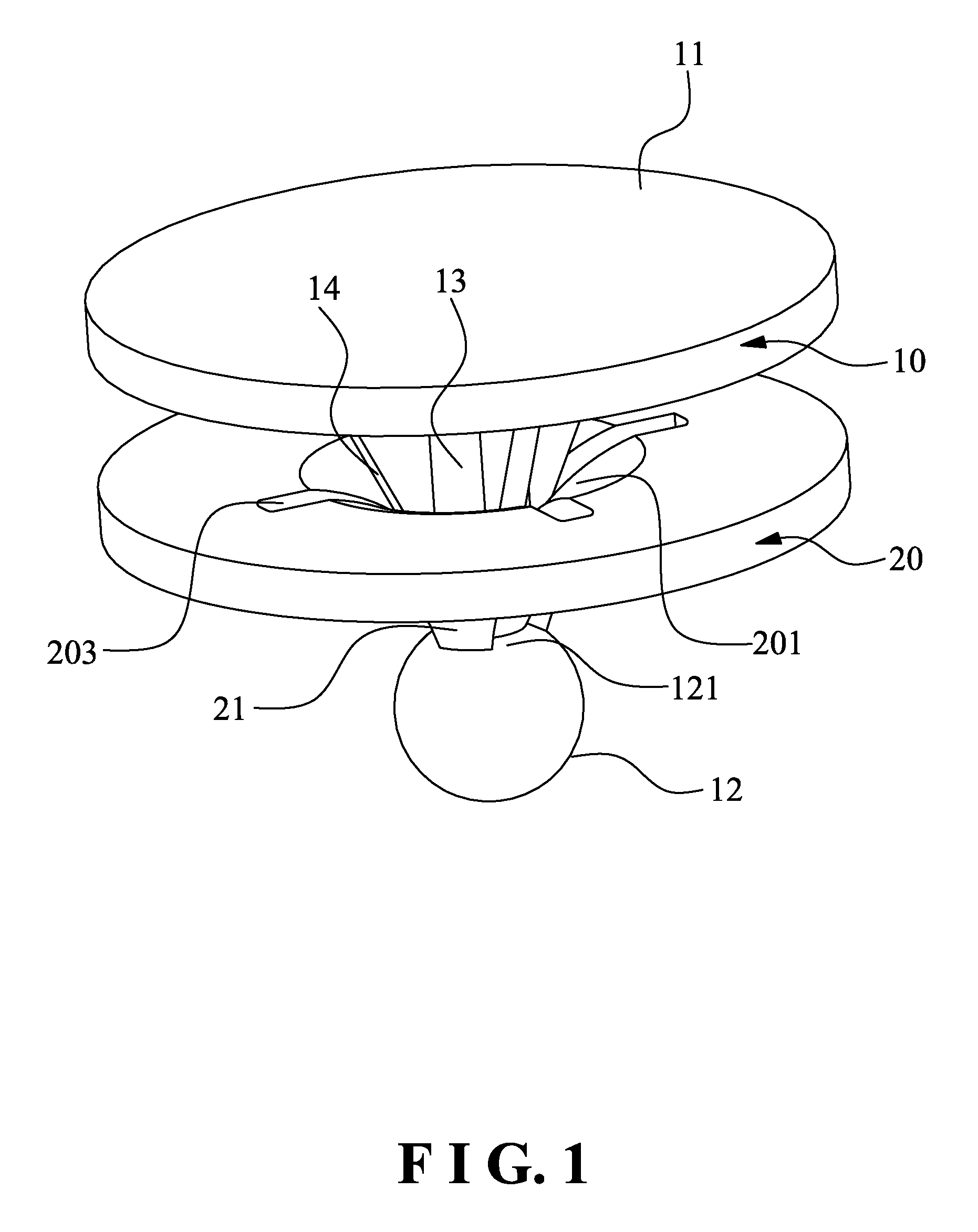
[0018]1. The clip member is provided with the plurality of resilient locking arms which are disposed in the same direction and the base member is provided with the buckle point. The free ends of the resilient locking arms are to lean against the inner end of the buckle point to achieve a self-locking connection of the base member and the clip member. The structure of present invention is simple. When packing a product, the two sheets of material are only required to have holes. The buckle point is inserted through the holes and coupled to the clip member so as to fix the two sheets of material. When detached, the connection of the buckle point and the buckle pin is cut off so as to detach the base member from the clip member. It is easy and convenient to use and operate the present invention, without the need to use a special apparatus. This can lower the packing cost.
[0019]2. The buckle pin is provided with the reinforcement ribs to enhance the connection of the buckle base and the buckle pin, such that the base member and the clip member can be connected firmly and reliably to enhance the quality of packing.
[0020]3. The resilient locking arms each have the curved guide surface to cooperate the spherical buckle point, so that the buckle point can easily slide out from the passage surrounded by the free ends of the resilient locking members. The assembly is simple and quick.

Problems solved by technology

The disadvantage of the clamshell is having to use a special welding machine to weld the two pieces together.
For small volume users, this might prove to be economically impossible.
Occasionally, staples are used to connect the two clear plastic, it gives a very poor image on the product.
Even though clamshells provide very good protection for the product, opening a clamshell can be a tough job for the consumer if the edges are completely sealed.

Method used


Image

  • Self-Locking Fastener
  • Self-Locking Fastener
  • Self-Locking Fastener

Examples


Embodiment Construction

[0027]Embodiments of the present invention will now be described, by way of example only, with reference to the accompanying drawings.

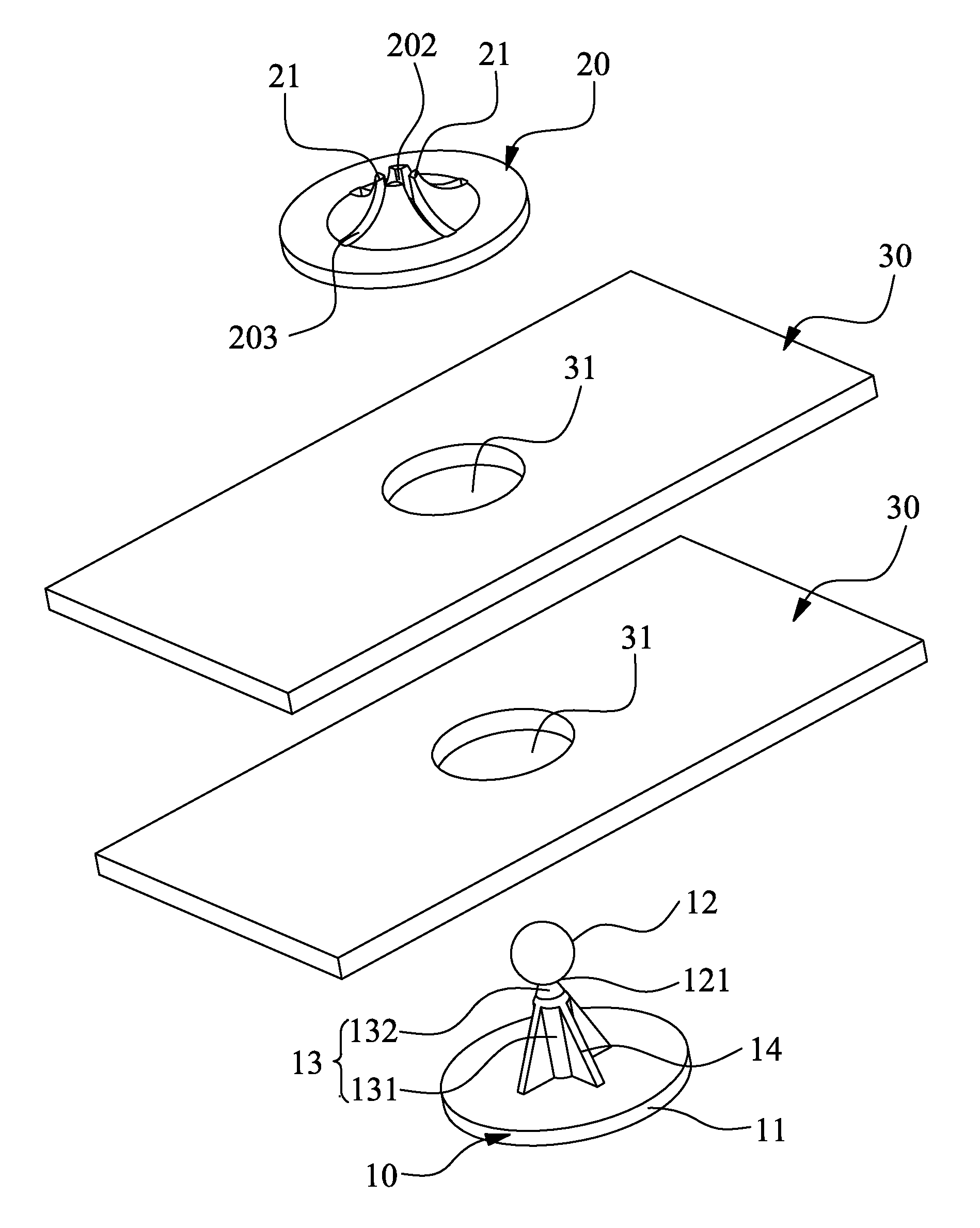
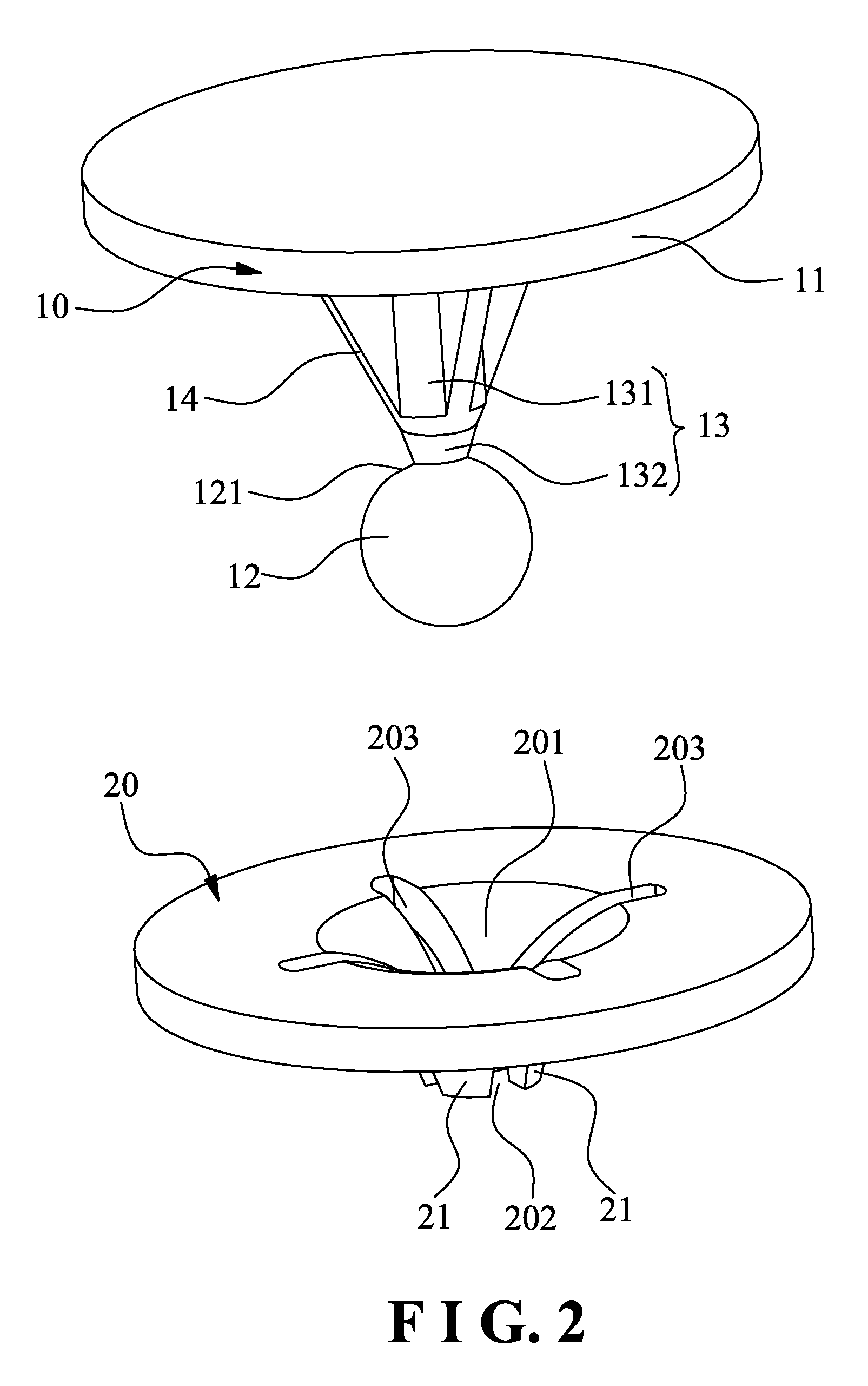
[0028]As shown in FIG. 1 through FIG. 5, the self-locking fastener according to a preferred embodiment of the present invention comprises a base member 10 and a clip member 20 mounted to the base member 10.

[0029]As shown in FIG. 1 and FIG. 2, the base member 10 is made of plastic. The base member 10 comprises a buckle base 11, a buckle point 12, and a buckle pin 13 which is connected between the buckle base 11 and the buckle point 12. The buckle base 11 is in a disk shape. The buckle point 12 is a sphere. The shape of the buckle point 12 is not limited to a sphere, which can be a cone or other shapes. The spherical buckle point 12 is conveniently mounted to the clip member 20. The buckle pin 13 has a base portion 131 and a connection portion 132 which extends from the base portion 131 and is tapered toward the buckle point 12. The base portion 131 is ...


PUM


Abstract

A self-locking fastener includes a base member and a clip member. The base member includes a buckle base, a buckle point and a buckle pin. The clip member includes a plurality of resilient locking arms disposed toward one side thereof. When the clip member is coupled to the base member, the buckle point of the base member extends out along the resilient locking arms. The resilient locking arms are fitted on the buckle pin. Free ends of the resilient locking arms lean against the inner end of the buckle point to stop the buckle point from sliding out along the resilient locking arms. Through the resilient locking arms and the buckle point, the free ends of the resilient locking arms are to lean against the inner end of the buckle point to achieve a self-locking connection of the base member and the clip member. The structure of present invention is simple. When packing a product, the two sheets of material are only required to have holes. The buckle point is inserted through the holes and coupled to the clip member so as to fix the two sheets of material. When detached, the connection of the buckle point and the buckle pin is cut off so as to detach the base member from the clip member. It is easy and convenient to use and operate the present invention, without the need to use a special apparatus. This can lower the packing cost.

Description

BACKGROUND OF THE INVENTION[0001]1. Field of the Invention[0002]The present invention relates to a self-locking fastener, and more particularly to one capable of connecting two sheets of material.[0003]2. Description of the Prior Art[0004]A popular way to package a consumer product is to use so called “Clamshell,” which consists of two clear plastic materials with the product in the middle. The two plastics are vacuum-formed in the shape of the product, and the edges are sealed with special welding machines. The two pieces can also be vacuum-formed together in one piece with the bottom folded leaving the other three sides open for sealing. The advantages of clamshell are the clear material displays the product without having to open the package, and security of product as one cannot open it without breaking the clamshell.[0005]The disadvantage of the clamshell is having to use a special welding machine to weld the two pieces together. This calls for an investment in machinery and we...

Claims


Application Information

Patent Timeline
Patent Type & Authority Applications(United States)
IPC IPC(8): A44B11/25
CPCF16B5/0642Y10T24/45995B65D63/1081F16B21/075
Inventor YUEN, KENNETH
Owner DONGGUAN MASTER INK CO LTD
Learn More