Six-way adjustable push latch

Active Publication Date: 2013-02-14
KWIKSET CORP
View PDF16 Cites 4 Cited by
  • Summary
  • Abstract
  • Description
  • Claims
  • Application Information

AI Technical Summary

Benefits of technology

[0007]It is, therefore, the primary object of the present invention to provide an improved adjustable backset lock or latch (collectively latch) mechanism which

Problems solved by technology

This takes significant effort and time.
Moreover, once the adjustable backset

Method used


Image

  • Six-way adjustable push latch
  • Six-way adjustable push latch
  • Six-way adjustable push latch

Examples


Embodiment Construction

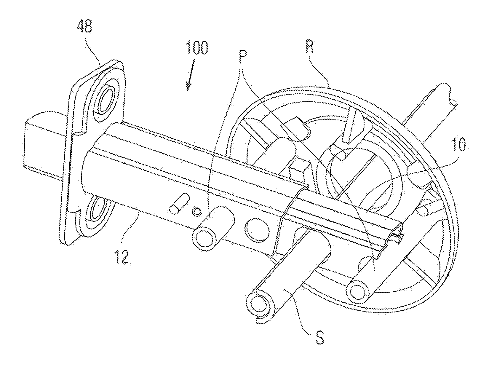
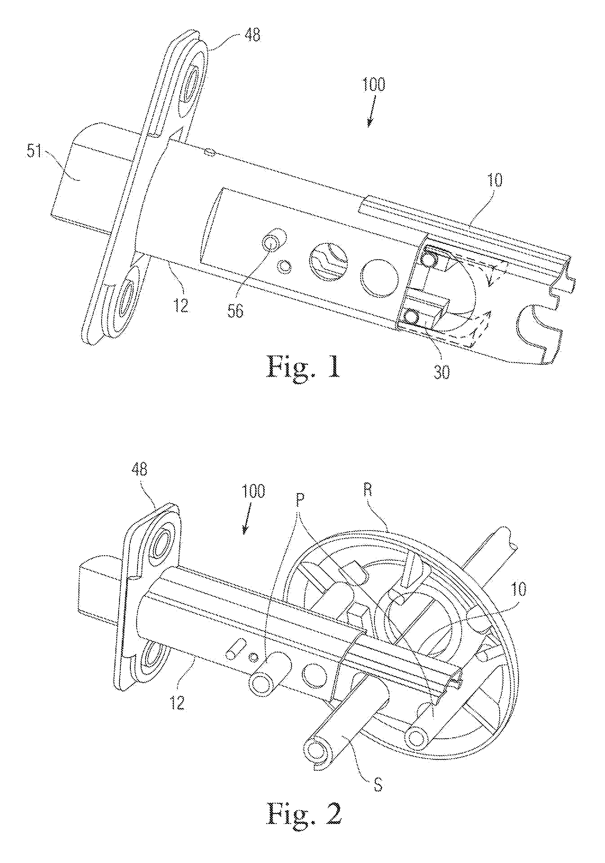
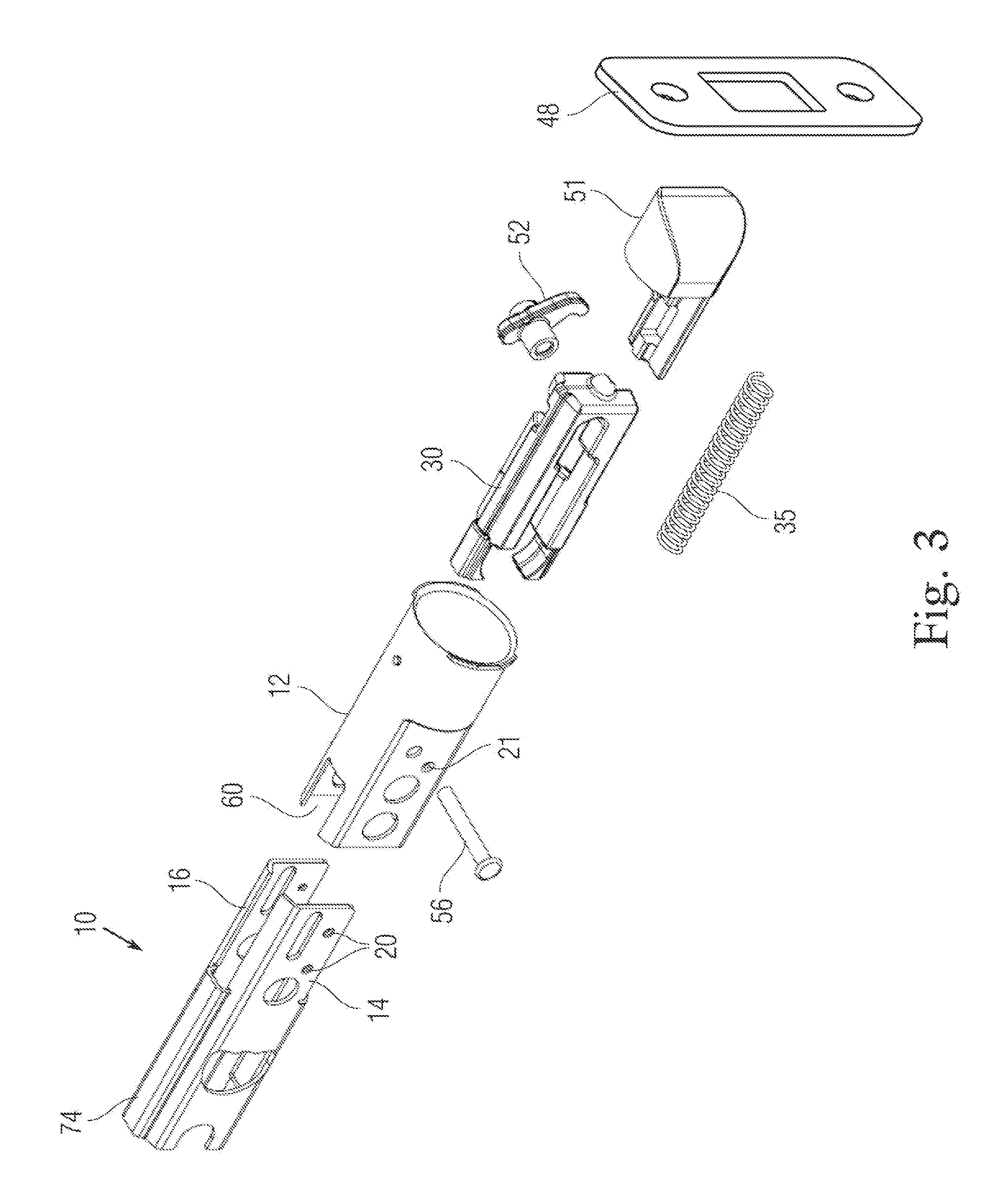
[0024]For the purposes of promoting an understanding of the principles of the invention, reference will now be made to the exemplary embodiment illustrated in the drawings and described below. The embodiment disclosed is not intended to be exhaustive or limit the invention to the precise form disclosed in the following detailed description. Rather, the embodiment is chosen and described so that others skilled in the art may utilize its teachings. It will be understood that the invention includes any alterations and modifications in the illustrated device, the methods of operation, and further applications of the principles of the invention which would normally occur to one skilled in the art to which the invention relates.

[0025]Directional terms such as left, right, up, down, top, bottom, inside, outside, inner, outer and the like are used for illustration and are not intended to be limiting. Additionally, although the present invention is disclosed in terms of a latch mechanism, a ...


PUM


Abstract

A latch assembly for insertion into an edge of a door and adjustable for actuation by a half-round spindle at either a first backset or a second backset. The latch has an inner casing non-rotatably received within an outer casing and slideable along an axis. The inner casing is provided with a transverse void substantially perpendicular to the sliding axis and is slideable between a first position in which the transverse void is aligned at the first backset and a second position is which the transverse void is aligned at the second backset. A slide within the casing is, without adjustment, engageable by the half-round spindle at either backset. A cam is rotatably mounted within the casing and engaged to the slide and to a bolt also within the casing. The bolt is slideably retractable into the casing by rotation of the cam in response to sliding of the slide. A spring biases the bolt to an extended position extend out from the casing.

Description

BACKGROUND OF THE INVENTION[0001]1. Field of the invention[0002]The present invention relates generally to lock and latch mechanisms and more particularly to latch mechanisms that are adjustable to accommodate differing door hardware backset dimensions.[0003]2. Description of the Background[0004]Entry doors on and in commercial and residential structures are commonly provided with a latching mechanism to a closed position when not locked, and / or a locking mechanism for securing them in the closed positions. In either case the retention and securing functions are accomplished by a bolt extending from the door and into the door frame to prevent movement. The bolt may be a spring actuated asymmetric latch bolt having a sloped face that is forced into the casing by contact with the strike plate to permit the door to latch closed on its own. Alternatively, a lockbolt with no sloped face may be manually extended or retracted. Such doors are equipped with hardware on their interior and ext...

Claims


Application Information

Patent Timeline
IPC IPC(8): E05C1/12E05B65/00E05B9/02E05C1/08
CPCE05B63/06Y10T292/0991Y10T292/1016Y10T292/1022Y10T292/62
Inventor BUI, JEANETTE VY
Owner KWIKSET CORP
Why Eureka
Try Eureka