Method of manufacturing a resin molding

a manufacturing method and resin technology, applied in the field of resin molding, can solve the problems of deteriorating recyclability, difficult to completely fill the cavity of molten resin or appropriately maintain, and difficult to mold the apparatus in a single injection step, so as to improve workability and work efficiency

Inactive Publication Date: 2007-11-27
CANON KK
View PDF8 Cites 3 Cited by
  • Summary
  • Abstract
  • Description
  • Claims
  • Application Information

AI Technical Summary

Benefits of technology

[0015]According to the present invention, the resin molding of a complicated shape can be efficiently and inexpensively manufactured without using any special dies or the like. Consequently, a very recyclable resin molding can be manufactured.
[0026]The number of the resin injecting nozzles and the number of the ejection plungers may correspond to the number of through-holes configured in the second molded part. Workability and working efficiency can be improved by simultaneously injecting the molten resin through all the through-holes.

Problems solved by technology

It is essentially difficult to mold this apparatus in a single injecting step.
This deteriorates recyclability.
Thus, depending on the shapes of a cavity in the joining portion 4 into which the molten resin is filled or the viscosity of the molten resin, it may be difficult to completely fill the molten resin into these cavitys or appropriately maintain the esthetics of the surface of the joining portion after the injection.
Thus, disadvantageously, a dedicated facility is required, thus increasing installation spaces and facility costs.
Furthermore, the injection molding apparatus itself is expensive and cumbersome to handle.

Method used


Image

  • Method of manufacturing a resin molding
  • Method of manufacturing a resin molding
  • Method of manufacturing a resin molding

Examples


Embodiment Construction

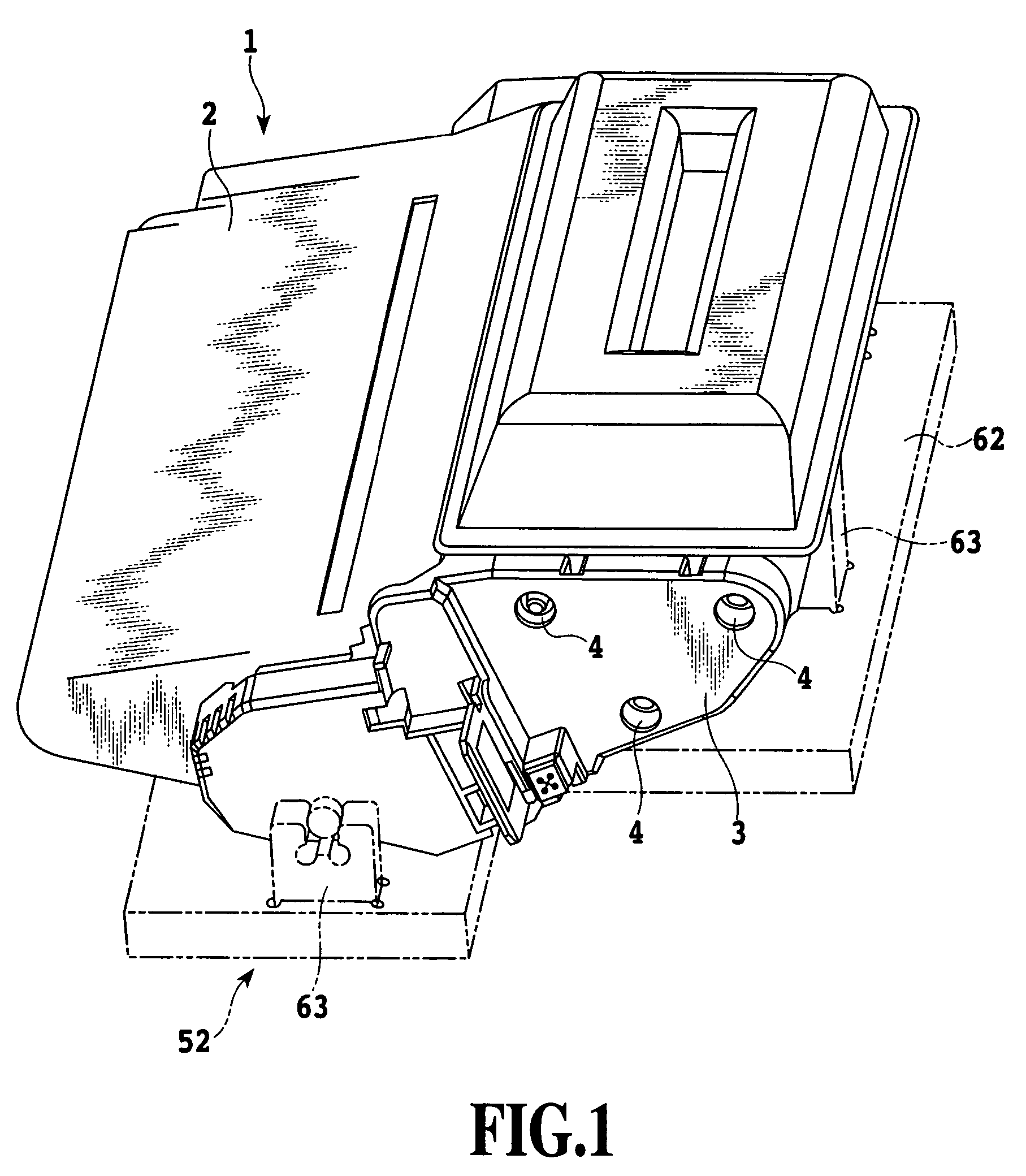
[0034]With reference to FIGS. 1 to 5, a detailed description will be given of an embodiment in which a method of manufacturing a resin molding according to the present invention is applied to the toner cartridge 1 of the electrophotograhic device as shown in FIG. 1. However, the present invention is not limited to this embodiment. It is possible to subject the embodiment to all alterations or modifications included in the concept of the present invention described in the specification. Thus, naturally enough, the present invention is applicable to other techniques belonging to the spirits of the present invention.

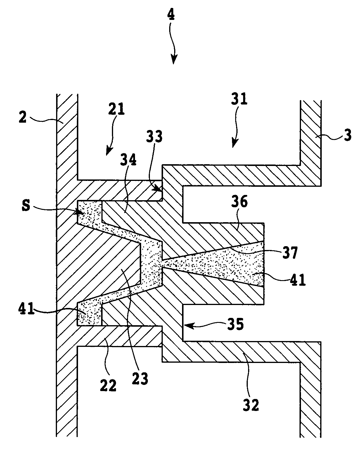
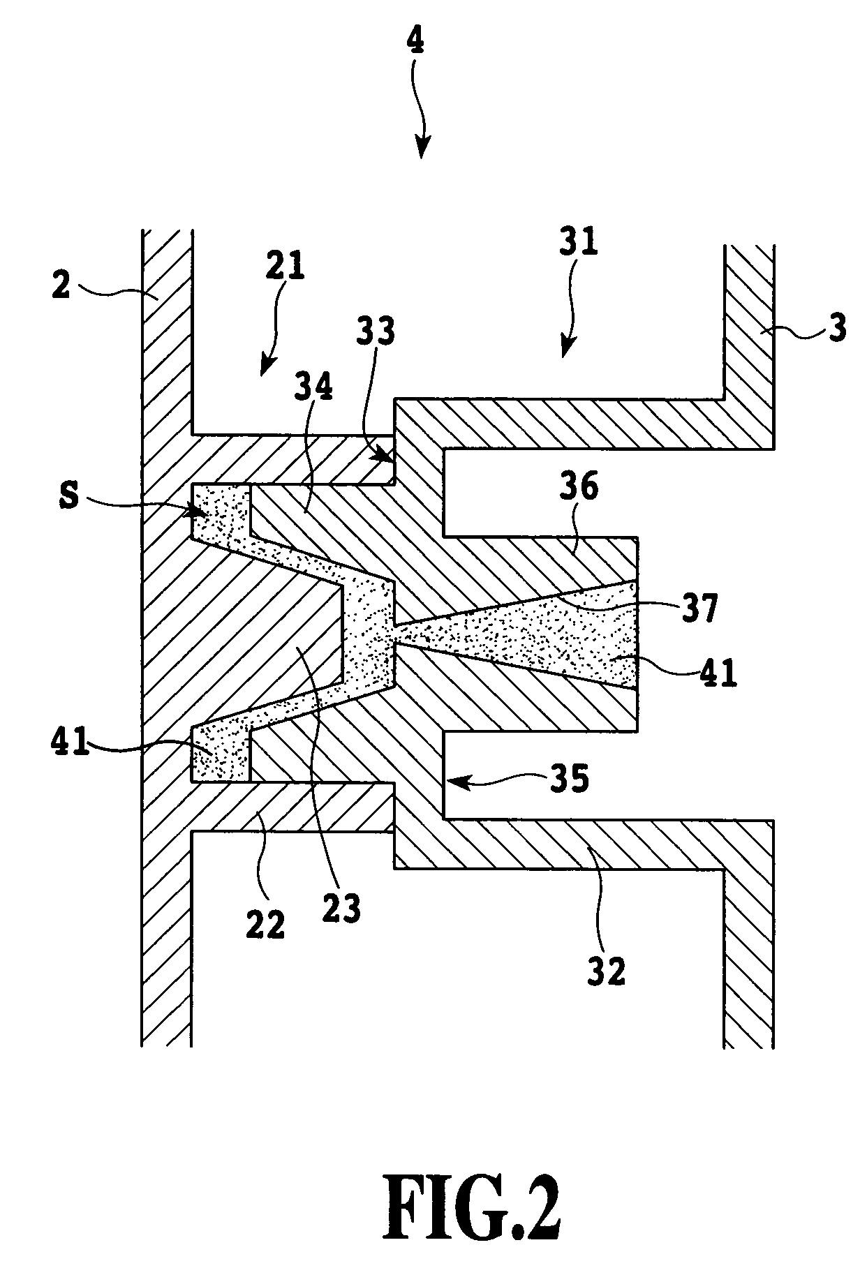
[0035]FIG. 1 shows the appearance of the toner cartridge 1 according to the present embodiment. FIG. 2 shows the sectional structure of the joining portion 4 between the cartridge main body 2 and the side cover 3. As described previously, the toner cartridge 1 according to the present embodiment comprises the cartridge main body 2 and the side cover 3 disposed at the side o...


PUM

PropertyMeasurementUnit
temperatureaaaaaaaaaa
viscosityaaaaaaaaaa
shapeaaaaaaaaaa

Abstract

A method of manufacturing a resin molding according to the present invention is made by joining first and second resin molded parts. The method includes molding a concave portion when molding the first part, molding a convex portion which has a through-hole in a central portion thereof when molding the second part, mating the concave portion with the convex portion so that a cavity in communication with one end of the through-hole is configured between the concave and convex portions, and holding, with a jig, the first and second parts which the cavity is configured therebetween. Additional steps include connecting a tip of an injection nozzle for injecting a molten resin into the cavity with the other end of the through-hole, and filling the molten resin into the through-hole and the cavity from the injection nozzle so that the concave and convex portions are integrally joined by the resin.

Description

[0001]This application claims priority from Japanese Patent Application No. 2003-027511 filed Feb. 4, 2003, which is incorporated hereinto by reference.BACKGROUND OF THE INVENTION[0002]1. Field of the Invention[0003]The present invention relates to a resin molding which is difficult to mold integrally and which is obtained by separately molding a plurality of resin molded parts each having a joining portion and mating these joining portions into one another to integrally join the molded parts together, as well as a method of manufacturing this resin molding and a resin injecting apparatus used for this method.[0004]2. Description of the Related Art[0005]It is contemplated that a resin molding that is difficult to mold integrally may be manufactured by separately pre-molding a plurality of resin molded parts, mating joining portions molded in these molded parts into one another, and injecting an adhesive or a resin into these joining portions to integrate the parts. For example, a ca...

Claims


Application Information

Patent Timeline
Patent Type & Authority Patents(United States)
IPC IPC(8): B29C45/14B29C45/26B29C45/00B29C65/42B29C65/70
CPCB29C45/0062B29C65/42B29C66/54B29K2105/0097Y10T428/24Y10T428/195Y10T428/19Y10T428/24529B29L2031/767B29C66/73921B29C66/71Y10T428/31504B29K2023/04B29K2023/10B29K2025/04B29K2069/00B29K2055/02B29K2071/12B29K2025/06B29K2023/12B29K2023/06
Inventor ABE, KENSHIROUSUZUKI
Owner CANON KK
Why Eureka
Try Eureka