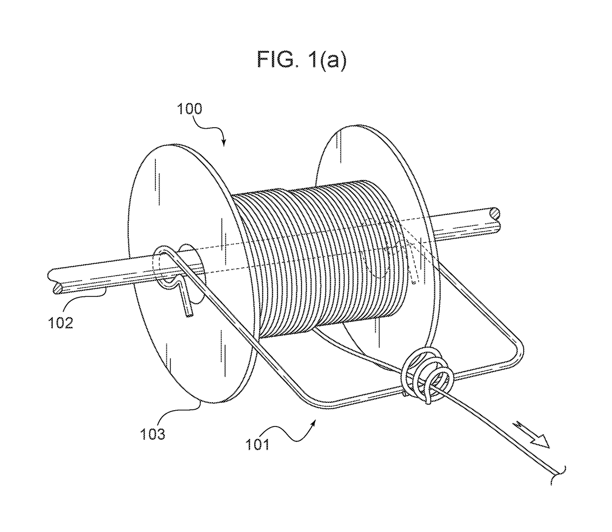
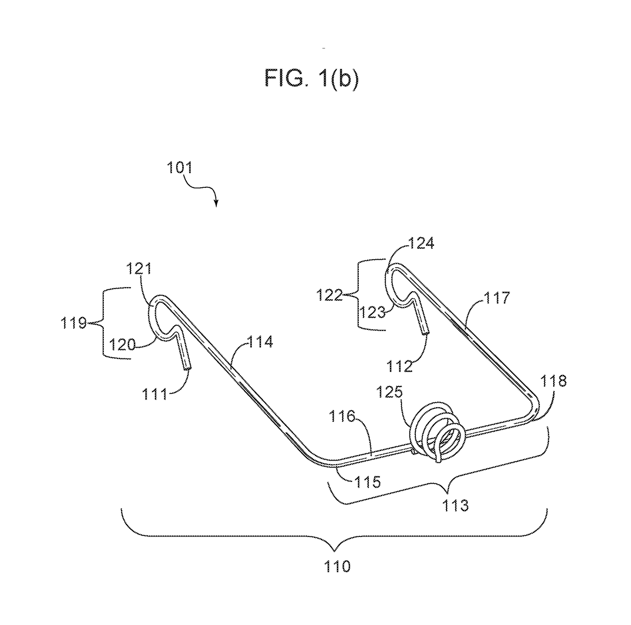
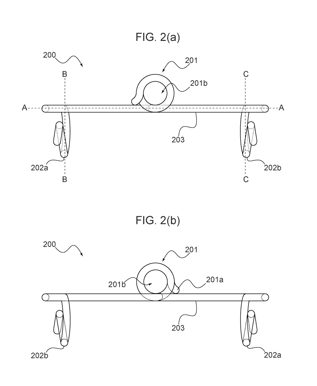
Wire spool guide

a wire spool and guide technology, applied in the direction of thin material processing, filament handling, transportation and packaging, etc., can solve the problems of limiting the versatility of devices, inefficient and unnecessarily time-consuming approach, and difficult detachment and reattachment to other spools, so as to reduce inherent tangling or snagging

Active Publication Date: 2019-01-03
BANDA EVAN
View PDF11 Cites 2 Cited by
  • Summary
  • Abstract
  • Description
  • Claims
  • Application Information

AI Technical Summary

Benefits of technology

[0015]To minimize the limitations in the prior art, and to minimize other limitations that will be apparent upon reading and understanding the present specification, the present inventi...

Problems solved by technology

Generally, these known devices implement wire-guiding elements or structures that require users to thread the spooled material through some tubular structure (for example such as an eye bolt) or similar single-opening structure that is circumferentially or perimetrically closed around the opening; as will be explained further below, this approach is inefficient and unnecessarily time consuming.
Some devices have features and characteristics that include moving components designed to attach to a spool and or adjust elements of the spool guide; these devices, however, are difficult to detach and reattach to other spools, thus limiting the versatility of the devices.
Yet other devices include entire assemblies for providing guides to numerous spools stored in such assemblies; again, making their use with various applications (i.e. varying types of spools) cumbersome, or simply impossible.
However, one problem with this device is that the wire is not easily kept in a center portion of the guide so as to fully protect the wire from becoming untangled or snagged by commonly damaged spool hubs.
Another problem with this device is that it is cumbersome to attach or couple to a spool; that is, it requires some assembly to attach to a spool—which is of course undesirably time-consuming.
Similarly, detaching the device from the spool is unnecessarily cumbersome.
Moreover, the guide mechanism is limited in that it requires threading and does not necessa...

Method used


Image

  • Wire spool guide
  • Wire spool guide
  • Wire spool guide

Examples


Embodiment Construction

[0042]In the following discussion that addresses a number of embodiments and applications of the present invention, reference is made to the accompanying drawings that form a part thereof, where depictions are made, by way of illustration, of specific embodiments in which the invention may be practiced. It is to be understood that other embodiments may be utilized and changes may be made without departing from the scope of the invention. Wherever possible, the same reference numbers are used in the drawings and the following description to refer to the same or similar elements.

[0043]In the following detailed description, numerous specific details are set forth by way of examples in order to provide a thorough understanding of the relevant teachings. However, it should be apparent to those skilled in the art that the present teachings may be practiced without such details. In other instances, well known structures, components and / or functional or structural relationship thereof, etc....


PUM


Abstract

The invention involves an improved wire spool guide including a frame that comprises adjacent legs for coupling with a support rod that typically traverses the center of a wire spool hub. Each leg includes a terminal end comprising a spring arm and rod-registering area configured to capture a portion of the rod while allowing the rod to rotate therein. In exemplary embodiments, each leg extends from an anterior support of the frame that is roughly perpendicular to both legs. A wire-guiding element extends substantially form a center portion of the anterior support. The wire-guiding element may be defined by a helical structure configured for allowing a portion of the wire to be weaved into the helical structure rather than having to be threaded through. The helical structure may include an incongruous element, which prevents the wire from tangling at an exit point of the wire-guiding element.

Description

PRIORITY NOTICE[0001]The present application claims priority under 35 U.S.C. § 119(e) to U.S. Provisional Patent Application Ser. No. 62 / 527,923 filed on Jun. 30, 2017, the disclosure of which is incorporated herein by reference in its entirety.TECHNICAL FIELD OF THE INVENTION[0002]The present invention relates generally to an improved wire spool guide. More specifically, the present invention relates to a wire spool guide including structural elements configured for removably coupling to a wire spool and guiding wire from the spool in a manner that reduces inherent tangling or snagging.COPYRIGHT AND TRADEMARK NOTICE[0003]A portion of the disclosure of this patent application may contain material that is subject to copyright protection. The owner has no objection to the facsimile reproduction by anyone of the patent document or the patent disclosure, as it appears in the Patent and Trademark Office patent file or records, but otherwise reserves all copyrights whatsoever.[0004]Certai...

Claims


Application Information

Patent Timeline
IPC IPC(8): B65H57/08B65H57/18
CPCB65H57/08B65H57/18B65H57/10B65H57/26
Inventor BANDA, EVAN
Owner BANDA EVAN
Why Eureka
Try Eureka