Embolic filter frame having looped support strut elements

a filter frame and support strut technology, applied in the field of embolism filter devices, can solve the problems of distal stasis/thrombosis, ischemic pain, cell ischemia and/or death, etc., and achieve the effects of increasing radial force, enhancing radial force, and increasing cross-sectional area

Active Publication Date: 2005-05-12
WL GORE & ASSOC INC
View PDF89 Cites 107 Cited by
  • Summary
  • Abstract
  • Description
  • Claims
  • Application Information

AI Technical Summary

Benefits of technology

[0014] The present invention is an improved embolic filter frame having looped support struts. The frame configuration of the present invention provides enhanced longitudinal compliance, improved sealing against a vessel wall, low profile delivery, and a short deployed length occupied by the frame and tethering elements.
[0015] To improve the apposition and sealing against a vessel wall, the present invention incorporates a filter support frame having “looped” support struts. The “looped” strut configuration enhances the radial force imparted onto a vessel wall without entailing the undesirable side effects previously described. The looped strut configuration also facilitates filter frame opposition when deployed in tortuous vascular anatomies. When in a tensioned or compressed delivery state, the looped support struts of the present invention assume an essentially longitudinal configuration and impart minimal radial force onto the catheter wall. The thickness of the catheter wall or radial constraint can therefore be minimized to increase flexibility, decrease the catheter profile, and enhance insertion trackabilty. During the deployment procedure, the looped support struts assume a looped configuration. Once in the deployed, looped configuration, the support struts exert a high degree of radial force onto the vessel wall, enhancing apposition and sealing. The looped support struts also provide a high degree of longitudinal compliance relative to conventional designs. In addition, the full length of the looped support struts is positioned very close to the filter element, which minimizes the overall deployed length of the filter media support element.
[0016] Among the important benefits of the present invention is that the deployed device of the present invention exhibits a low degree of “longitudinal” stiffness. Thus, in the deployed state, the device remains limp and compliant in the longitudinal direction. Consequently, minor longitudinal displacements of the support wire or catheter are not translated to the filter frame and vessel wall during guide wire manipulation.
[0017] Another beneficial feature of the present invention is that the looped struts and the central collar connecting the support struts to the support wire of the present invention are positioned essentially within the plane of the filter opening and, if desired, can even be positioned within the filter frame element itself. This improves the utility of the embolic filter of the present invention by reducing the overall deployed length of the filter support frame and allowing the filter to be deployed very close to the treatment site.

Problems solved by technology

In therapeutic vascular procedures, liberation of embolic debris (e.g., thrombus, clot, atheromatous plaque, etc.) can obstruct perfusion of the downstream vasculature, resulting in cellular ischemia and / or death.
Additionally, percutaneous transluminal coronary angioplasty (PTCA) with or without adjunctive stent placement, surgical coronary artery by-pass grafting, percutaneous renal artery revascularization, and endovascular aortic aneurysm repair have also been associated with complications attributable to atheromatous embolization.
The principle drawback of occlusion balloon techniques stems from the fact that during actuation, distal blood flow is completely inhibited, which can result in ischemic pain, distal stasis / thrombosis, and difficulties with fluoroscopic visualization due to contrast wash-out through the treated vascular segment.
The device also lacks longitudinal compliance.
Thus, inadvertent movement of the catheter results in longitudinal translation of the filter, which can cause damage to the vessel wall and liberate embolic debris.
During positioning within a vessel, the filter material is not fully constrained so that, as the device is positioned through and past a clot, the filter material can potentially snag clot material creating freely floating emboli prior to deployment.
The device also lacks longitudinal compliance.
This device also lacks substantial longitudinal compliance.
This device has the additional drawback of having an extended length due to the longitudinally oriented strut configuration of the tapered frame.
This extended length complicates the navigation and placement of the filter within tortuous anatomy.
The filter, however, may not seal around the interior vessel wall.
This umbrella-type device is shallow when deployed so that, as it is being closed for removal, particles have the potential to escape.
In summary, disadvantages associated with predicate devices include lack of longitudinal compliance, extended deployed length of the frame and associated tethering elements, and inadequate apposition and sealing against a vessel wall.
Without longitudinal compliance, inadvertent movement of the filter catheter or support wire can displace the deployed filter and damage a vessel wall and / or introgenic vascular trauma, or, in extreme cases, result in the liberation of embolic debris.
Inadequate filter apposition and sealing against a vessel wall has the undesirable effect of allowing emboli passage.
These methods typically have the undesirable side effects of degrading the longitudinal compliance, adding to the compressed delivery profile, and, in some cases, increasing the deployed length.
Some methods used to increase the radial force (for example, stiffer support frames) have the additional drawback of requiring thicker-walled, larger profile, delivery catheters.

Method used


Image

  • Embolic filter frame having looped support strut elements
  • Embolic filter frame having looped support strut elements
  • Embolic filter frame having looped support strut elements

Examples


example 1

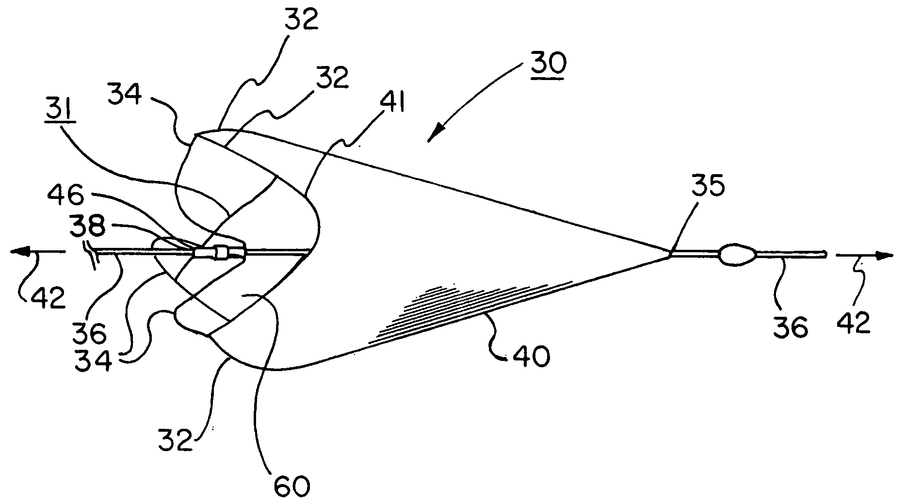
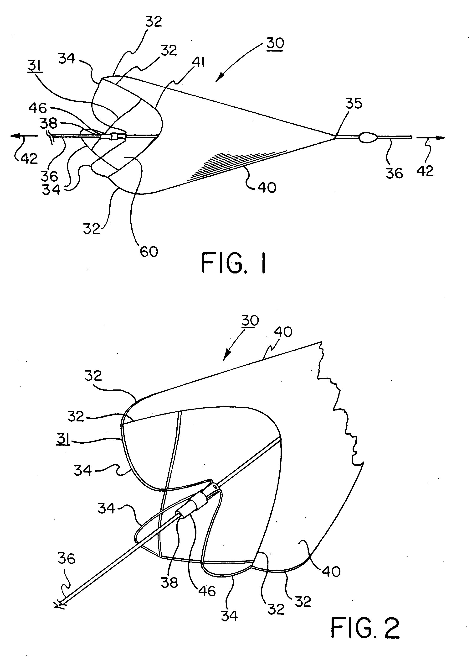
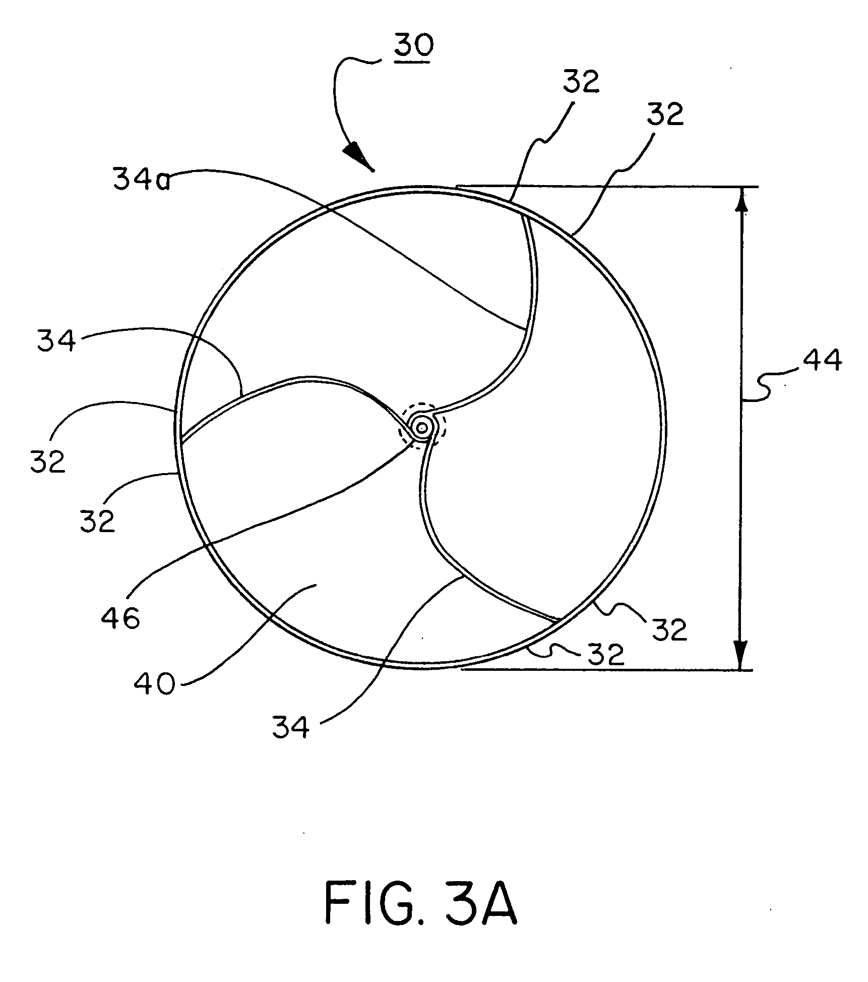
[0096] As shown in FIG. 15, a 0.9 mm nitinol tube 104, with a wall thickness of approximately 0.09 mm (obtained from SMA Inc, San Jose, Calif.) was laser cut by Laserage Technologies Inc, Waukegan, Ill., to form a frame configuration of a single, undulating, integral, 6 apex ring. The frame included radiopaque marker housings 106 at each distal apex and tether or strut elements 34 extending from each proximal apex 108 and converging at the opposite end in a “collar”46 of uncut parent material. This frame was then lightly grit blasted at 30 psi with 20-micron silicon carbide media in a grit blasting machine (Model MB1000 available from Comco Inc, Burbank, Calif.). The frame was then gently slid up a tapered mandrel until it achieved a functional size of approximately 6mm.

[0097] The frame and mandrel were then subjected to an initial thermal treatment to set the geometry in an initial, tapered (conical) configuration in an air convection oven (Carbolite Corporation, Sheffield, Englan...


PUM

PropertyMeasurementUnit
angleaaaaaaaaaa
angleaaaaaaaaaa
bend anglesaaaaaaaaaa

Abstract

An improved embolic filter frame having looped support struts. The frame configuration provides enhanced longitudinal compliance, improved sealing against a vessel wall, low profile delivery, and a short deployed length. The looped support struts have a high degree of “radial” stiffness with a low degree of “longitudinal” stiffness. In the deployed state, the frame exerts a relatively high stress onto a vessel wall to maintain an effective seal, yet remains compliant in the longitudinal direction. Minor displacements of the support wire or catheter are therefore not translated to the filter. The looped support struts elongate when tensioned and assume a compressed and essentially linear form. While constrained in this linear state by a delivery catheter, the support struts exert minimal stress onto the delivery system. The overall delivery profile and stiffness are therefore reduced. When the delivery catheter constraint is removed during deployment, the struts “snap open” and assume a looped configuration which exert a high degree of force onto the vessel wall, creating an enhanced filter to vessel wall seal. In addition, the looped struts and the central collar connecting the support struts to the support wire, are positioned essentially within the plane of the filter opening. The overall deployed length of the embolic filter is therefore reduced.

Description

CROSS REFERENCE TO RELATED APPLICATIONS [0001] This application is a continuation of U.S. patent application Ser. No. 10 / 273,859 filed Oct. 17, 2002.FIELD OF THE INVENTION [0002] The invention relates to embolic filter devices for placement in the vasculature and in particular, self-expanding frames used to support embolic filter elements. BACKGROUND OF THE INVENTION [0003] Embolic protection is a concept of growing clinical importance directed at reducing the risk of embolic complications associated with interventional (i.e., transcatheter) and surgical procedures. In therapeutic vascular procedures, liberation of embolic debris (e.g., thrombus, clot, atheromatous plaque, etc.) can obstruct perfusion of the downstream vasculature, resulting in cellular ischemia and / or death. The therapeutic vascular procedures most commonly associated with adverse embolic complications include: carotid angioplasty with or without adjunctive stent placement; and revascularization of degenerated saph...

Claims


Application Information

Patent Timeline
Patent Type & Authority Applications(United States)
IPC IPC(8): A61BA61F2/01A61M29/00
CPCA61F2/013A61F2002/018Y10T29/49826A61F2230/0067B23P11/00A61F2230/0006A61F2/0105
Inventor CULLY, EDWARD H.VONESH, MICHAEL J.
Owner WL GORE & ASSOC INC
Why Eureka
Try Eureka