Compression apparatus

a compression device and apparatus technology, applied in the field of vascular therapy, can solve the problems of affecting the comfort of patients, affecting the recovery of patients, so as to facilitate quick disconnect, reduce bulk, and improve comfort and compliance to patients.

Active Publication Date: 2005-08-25
KPR U S LLC
View PDF99 Cites 157 Cited by
  • Summary
  • Abstract
  • Description
  • Claims
  • Application Information

AI Technical Summary

Benefits of technology

[0009] Accordingly, a compression apparatus is provided that reduces bulk and is not cumbersome during use to improve comfort and compliance to a patient for overcoming the disadvantages and drawbacks of the prior art. Desirably, the compression apparatus includes a removable portion to achieve the advantages of the present disclosure. Most desirably, the compression apparatus has a valve connector that facilitates quick disconnect from a pressurized fluid source. The compression apparatus is easily and efficiently fabricated.
[0010] The compression apparatus, in accordance with the principles of the present disclosure, includes a thigh length compression sleeve that converts to a knee length sleeve via tearing away or otherwise removing the thigh bladder and disconnecting the thigh bladder air supply line. In one embodiment, the thigh bladder air supply line will remove easily along with the thigh bladder, attaching at or near the point where the thigh bladder is removed from the sleeve. This would allow for a single motion to accomplish both removing of the thigh bladder and the thigh bladder supply line. The convertible sleeve allows the patient to use a more comfortable sleeve (knee vs. thigh) as risk for DVT decreases after surgery. This provides practitioners with various options while using a single apparatus.
[0011] In another embodiment, the compression apparatus is perforated for improved compliance and comfort with the patient during the overall length of time for wearing the apparatus. It is contemplated that the apparatus can be used with both nomadic and / or stationary compression systems. A pressurized fluid source continues to deliver pressurized fluid after removal of the valve. The pressurized fluid source can signal a high alarm if there are kinks in the tubing and a low alarm if there are leaks in the tubing. The compression apparatus is sequentially activated by increasing pressure through the tubes to correspond with the three portions of the sleeve. The distal end is the ankle bladder (high pressure), the proximal end is the thigh bladder (low pressure). The pressurized fluid source pumps air to the sleeve in a 60 second cycle with 11 seconds being compression and the rest being decompression.

Problems solved by technology

For example, when blood circulation in these veins is retarded due to illness, injury or inactivity, there is a tendency for blood to accumulate or pool.
A major risk associated with this condition is interference with cardiovascular circulation.
A pulmonary emboli can form blocking a main pulmonary artery, which may be life threatening.
These known devices may suffer from various drawbacks due to their bulk and cumbersome nature of use.
These drawbacks reduce comfort, compliance and may disadvantageously prevent mobility of the patient as recovery progresses after surgery.

Method used


Image

  • Compression apparatus
  • Compression apparatus
  • Compression apparatus

Examples


Embodiment Construction

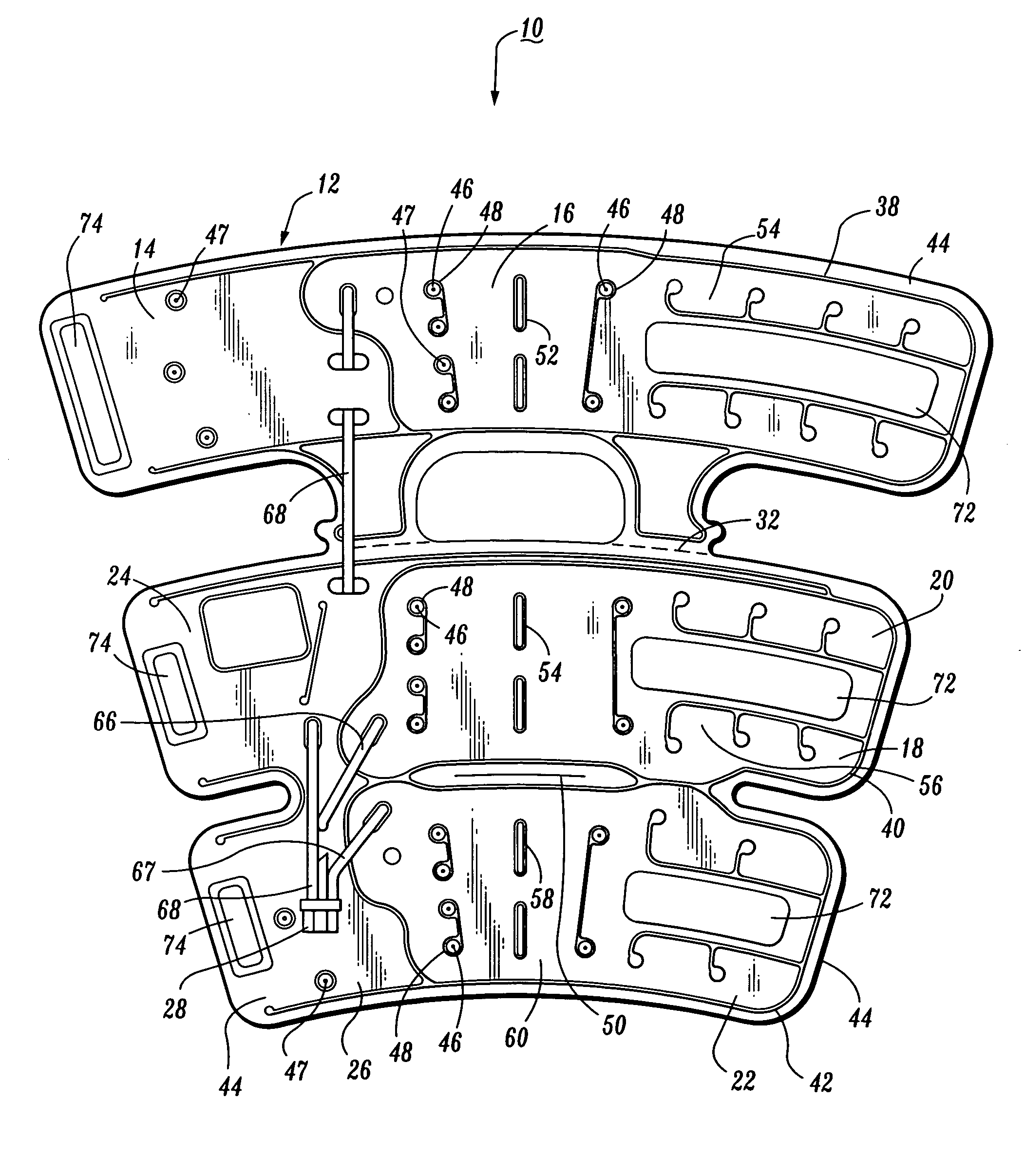
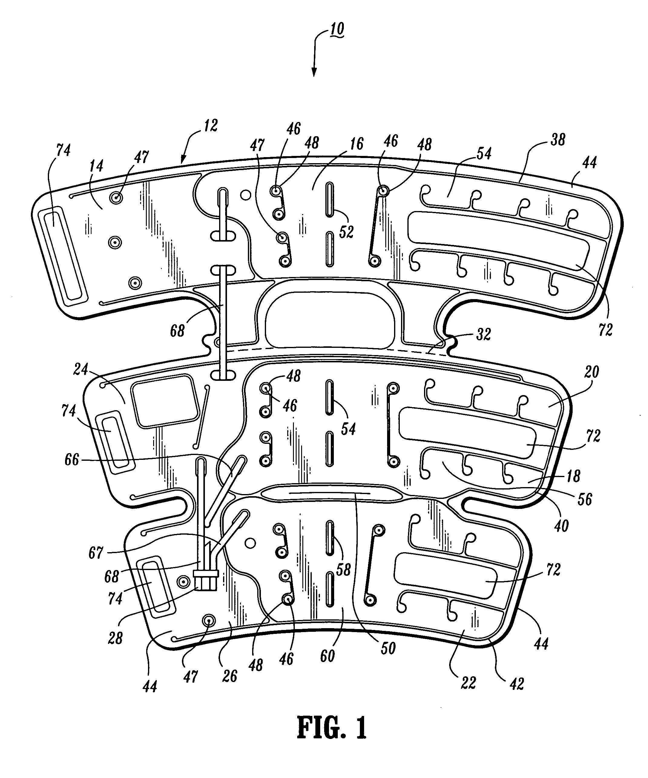
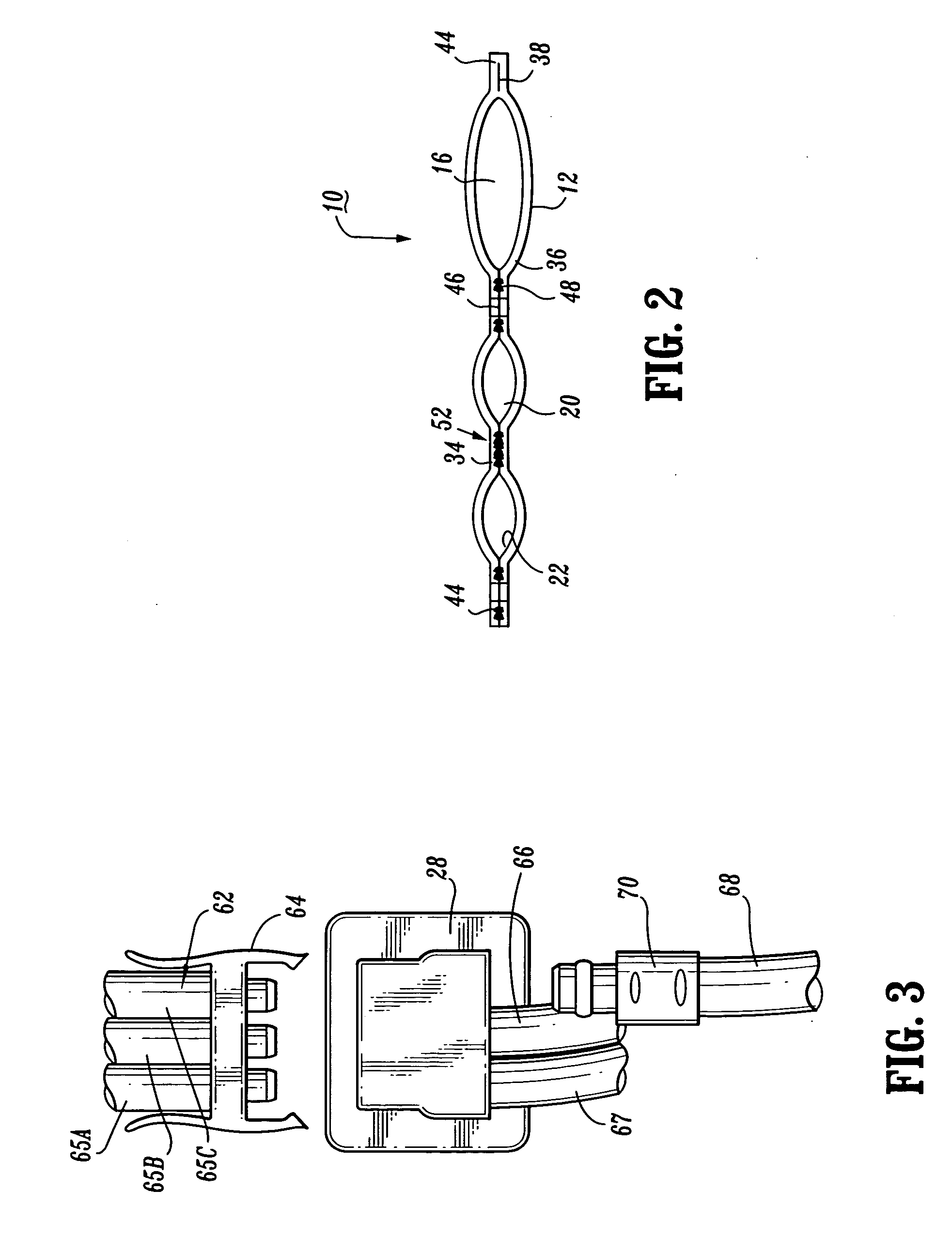
[0033] The exemplary embodiments of the compression apparatus and methods of operation disclosed are discussed in terms of vascular therapy including a prophylaxis compression apparatus for application to a limb of a body and more particularly in terms of a compression apparatus having removable portions. It is contemplated that the compression apparatus may be employed for preventing and overcoming the risks associated with patient immobility. It is further contemplated that the compression apparatus alleviates the conditions arising from patient immobility to prevent for example, DVT, peripheral edema, etc. It is contemplated that the compression apparatus according to the present disclosure may be attributable to all types of venous compression systems, including, but not limited to a prophylaxis sequential compression apparatus. The term “prophylaxis sequential” shall not be construed as limiting the general venous compression apparatus described herein. It is envisioned that th...


PUM


Abstract

A compression apparatus is provided that includes a sleeve configured for disposal about a limb. The sleeve includes a first portion defining a first expandable chamber and a second portion defining a second expandable chamber and a third expandable chamber. The second portion includes a connector in fluid communication with a pressurized fluid source and the chambers thereby facilitating fluid communication between the pressurized fluid source and the chambers. The first portion is removable from the second portion. The first portion may be connected to the second portion via a perforated attachment. The sleeve may define at least one ventilation opening. The connector can communicate with the chambers via a tubular pathway. The sleeve may be convertible from a length extending from below a knee to above the knee, to a length extending solely below the knee.

Description

BACKGROUND [0001] 1. Technical Field [0002] The present disclosure generally relates to the field of vascular therapy for application to a limb of a body, and more particularly, to a compression apparatus having removable portions. [0003] 2. Description of the Related Art [0004] A major concern for immobile patients and persons alike are medical conditions that form clots in the blood, such as, deep vein thrombosis (DVT) and peripheral edema. Such patients and persons include those undergoing surgery, anesthesia, extended periods of bed rest, etc. These blood clotting conditions generally occur in the deep veins of the lower extremities and / or pelvis. These veins, such as the iliac, femoral, popiteal and tibial return deoxygenated to the heart. For example, when blood circulation in these veins is retarded due to illness, injury or inactivity, there is a tendency for blood to accumulate or pool. A static pool of blood is ideal for clot formations. A major risk associated with this c...

Claims


Application Information

Patent Timeline
Patent Type & Authority Applications(United States)
IPC IPC(8): A61F5/00A61F5/34A61H7/00A61H19/00A61H23/04
CPCA61F5/34A61H9/0078Y10S128/20A61H2201/1697A61H2205/10
Inventor TORDELLA, ELISETESLUK, CHRISTOPHERBOCK, MALCOLM
Owner KPR U S LLC
Why Eureka
Try Eureka