Bioabsorbable self-expanding endolumenal devices

a bioabsorbable, endolumenal technology, applied in the field of implantable medical devices, can solve the problems of adverse interaction with the metallic implant, negative impact a subsequent procedure may have on the patient, and strong magnetic field produced by the magnetic resonance imaging (mri) machine, and achieve the effect of enhancing tissue compliance of the devi

Inactive Publication Date: 2006-02-02
WL GORE & ASSOC INC
View PDF31 Cites 157 Cited by
  • Summary
  • Abstract
  • Description
  • Claims
  • Application Information

AI Technical Summary

Benefits of technology

[0033] Though sufficiently strong to resist radially compressive forces from tissue in which devices of the present invention are implanted, the devices have a Young's modulus equal to or less than the tissue in which the devices are implanted. Accordingly, tubular devices of the present invention have integral non-elongating frameworks with a Young's tensile modulus of approximately than 2.1×10⁶ Pascals when evaluated longitudinally in an open, uncompressed, and unrestrained (i.e. fully deployed) configuration. Devices of the present invention are very compliant with implanted tissue as a consequence. A multiplicity of fenestrations is provided in the integral framework to further en

Problems solved by technology

Of particular concern in leaving a metallic implant in a patient is the negative impact a subsequent procedure may have on the patient as a result of the implanted device.
For example, the strong magnetic field produced by a magnetic resonance imaging (MRI) machine can adversely interact with the metallic implant.
Also, the presence of a chronically implanted device can cause abrasions or erosions to tissue in which the device is implanted.
Additionally, a subsequent endoluminal procedure can also result in an adverse encounter, or interaction, with a previously implanted device.
Unfortunately, when the polymeric material used to make the stent is placed inside a body conduit and raised above its melt temperature to undergo a re-modeling process, any inconsistency or inadequacy in thermal transfer from the heated balloon to the device as it is deployed can cause irregular and potentially unpredictable device deformations.
Consequently, implantable medical devices intended for use as degradable stents or other temporary scaffoldings for a body conduit made of poly(ε-caprolactone), or similar homopolymers that require a thermal softening or melting transition above normal human body temperature in order to expand, are likely to lack sufficient reliable mechanical strength to be practical devices.
The stent is described as expandable using a “thermally-assisted mechanical expansion process at a temperature between about 38 degrees centigrade and 55 degrees centigrade.” Hence, the Healy et al. stent does not expand at normal human body temperature of 37 degrees centigrade and is also described as risking a “potentially hazardous” fracture if expansion is attempted in the brittle and glassy state found below the Tg of the stent.
Devices requiring in situ application of heat above normal human body

Method used


Image

  • Bioabsorbable self-expanding endolumenal devices
  • Bioabsorbable self-expanding endolumenal devices
  • Bioabsorbable self-expanding endolumenal devices

Examples


example 1

[0108] This example describes the preparation of an extrudate made of a bio-absorbable polymer suitable for use in the present invention. The extrudate is subsequently extruded into a tubular shape for further processing into a device of the present invention.

[0109] A tri-block co-polymer of poly(glycolide) and poly(trimethylenecarbonate) having a weight to weight (w / w) ratio of 67% poly(glycolide) to 33% poly(trimethylenecarbonate) was acquired from Davis and Geck / United States Surgical (Manati, Puerto Rico—Lot #:01I01). This bioabsorbable PGA / TMC co-polymer, commonly referred to as polyglyconate, was provided with certification to its co-polymer ratio.

[0110] Upon receipt, approximately 25 mg of the PGA / TMC co-polymer was dissolved in 25 ml of hexafluoroisopropanol (HFIP). The produced dilute solution was found to possess an inherent viscosity (IV) of 1.41 dl / g when measured using an AUTOVISC™ I automated viscometer operating at 30 degrees centigrade.

[0111] Approximately 6 mg of...

example 2

[0114] This example describes the formation of a construction of a bioabsorbable polymeric material suitable for further processing into a device of the present invention. The construction was extruded into a tubular shape with a 0.5 inch, 24:1, screw extruder (Randcastle Extrusion Systems, Inc., Cedar Grove, N.J.). The extruder had a three-stage screw.

[0115] The process was begun by heating approximately 200 grams of the PGA / TMC block co-polymer of Example 1 overnight under vacuum at 130 degrees centigrade to dry the co-polymer. The dried co-polymer was then placed into the extruder.

[0116] The extruder was programmed to provide a temperature profile that achieves a melt temperature between 205 degrees and 210 degrees centigrade with a die temperature between 205 degrees and 210 degrees centigrade. The extruder melted and pumped the polymer through a Genca (Clearwater, Fla.) tubing die designed to produce a draw ratio of about 5:1 with a draw ratio balance of about 1.00.

[0117] Th...

example 3

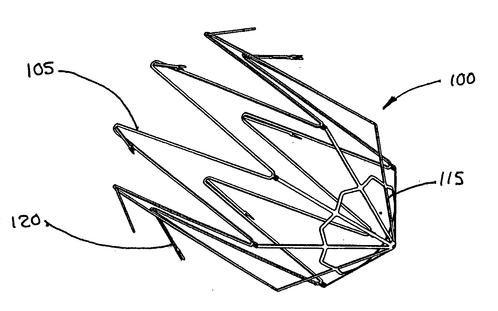
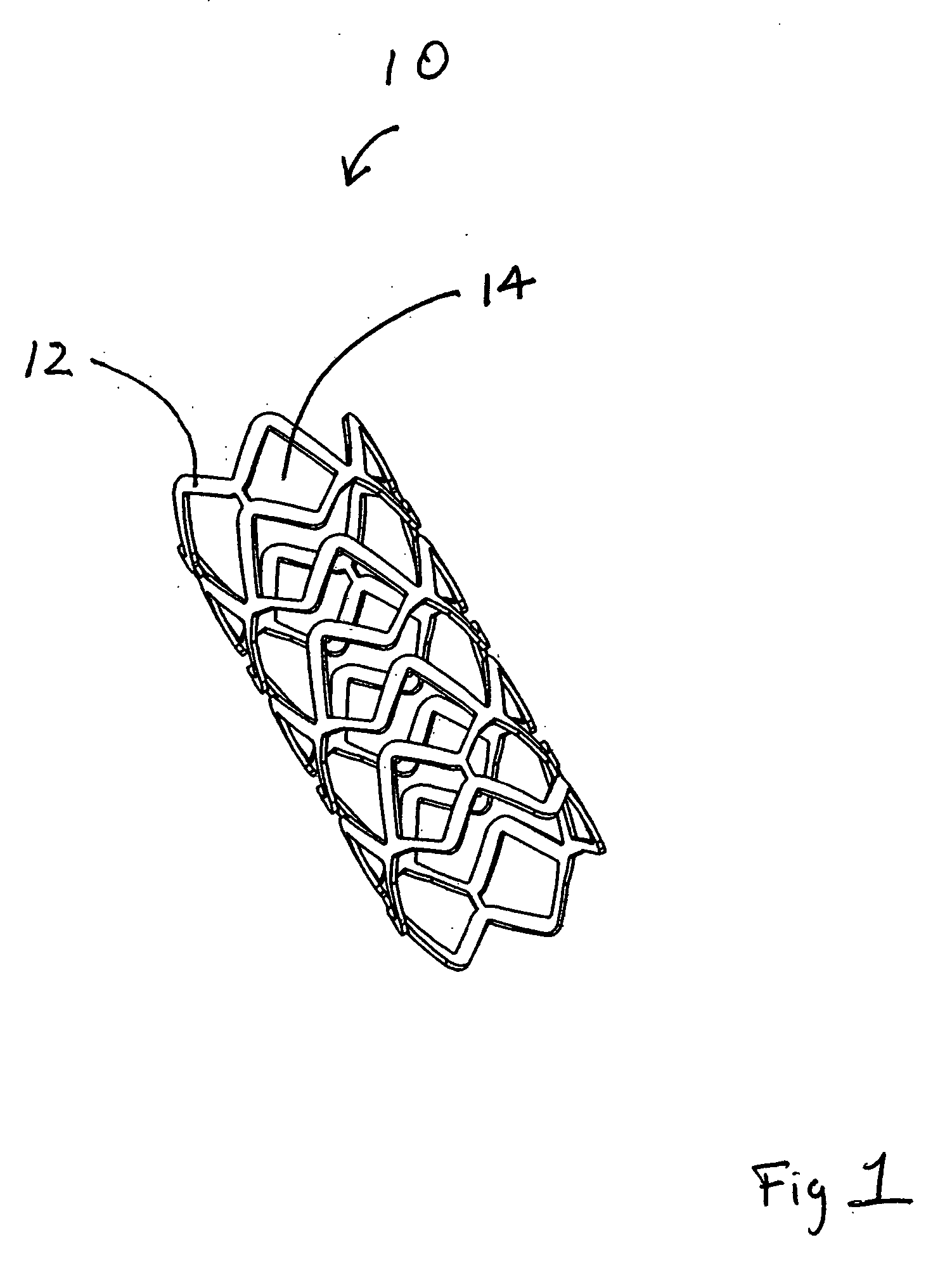
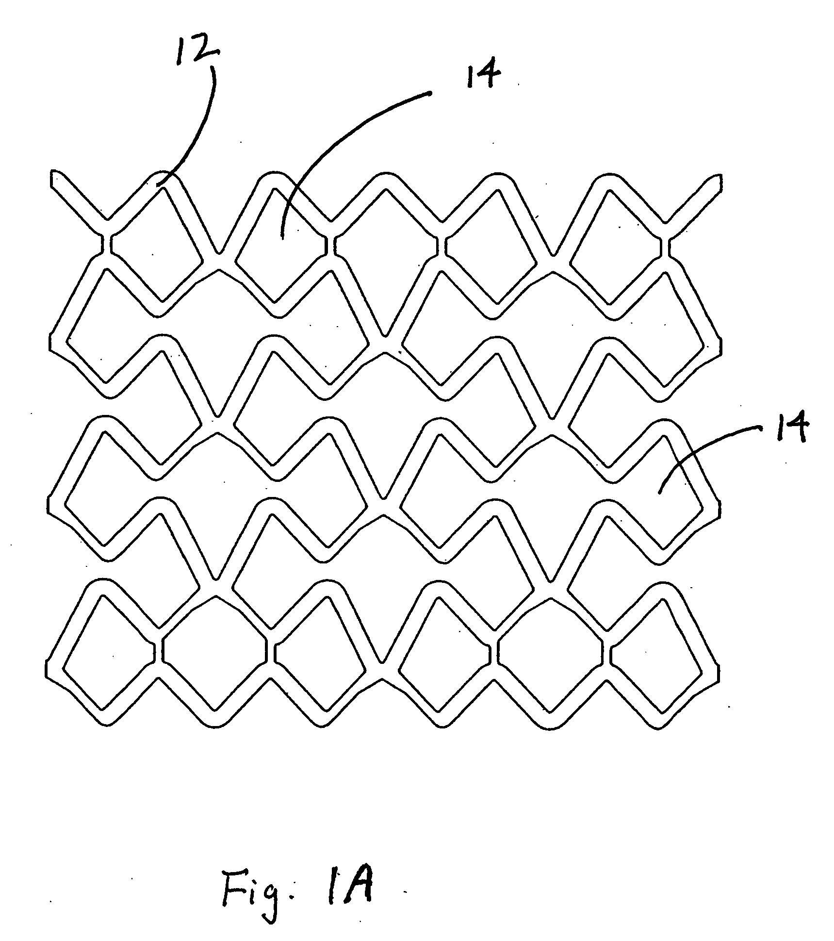
[0120] This example describes forming fenestrations (14) in the tubular construction (16) of Example 2 with an excimer laser. When the fenestrations were formed in the construction, a device of the present invention (10) comprising an integral self-expanding, non-elongating, bioabsorbable framework (12) was formed. The finished device once sterilized can serve as a bioabsorbable support for a body conduit.

[0121] A 248 nm gas excimer laser (available from J. P. Sercel Associates, Inc., Hollis, N.H., system JPSA 100-01-INV024, model IX1000) was used to form a series of fenestrations (14) in the tubular construction (16). The laser was set to produce a 110 milli-joules light beam, repeatedly pulsed at 200 Hz. The energy density at the device was 2 Joules per square centimeter.

[0122] The laser was fitted with attachments that permitted a chuck for holding and rotating a mandrel to be attached to the laser. The chuck was driven by a rotary servomotor. A base tube for a device of the pr...


PUM

PropertyMeasurementUnit
Angleaaaaaaaaaa
Forceaaaaaaaaaa
Compositionaaaaaaaaaa

Abstract

The present invention is directed to bioabsorbable self-expanding medical devices for use inside or outside body conduits that self-expand at, or below, normal human body temperature without requisite for a polymeric thermal transition

Description

FIELD OF THE INVENTION [0001] The present invention is directed to implantable medical devices. In particular, the invention is directed to self-expanding bioabsorbable endolumenal devices. BACKGROUND OF THE INVENTION [0002] A variety of implantable medical devices have been developed to treat diseased, injured, or deformed body conduits. In cases where malfunctioning body conduits have reduced inner diameters, there is usually reduced flow of vital fluid or gas through the conduits. In extreme cases, the malfunctioning conduits are occluded. Implantable medical devices used to open and / or expand, or to otherwise treat obstructed or constricted body conduits often reside in the conduits for a period of time following deployment of the devices. The devices serve primarily as mechanical supports inside the malfunctioning conduits to help maintain the conduits in more open, or patent, conditions. [0003] These types of implantable medical devices are usually threaded through a healthy b...

Claims


Application Information

Patent Timeline
IPC IPC(8): A61F2/06
CPCA61B17/12022A61F2230/0054A61B17/1214A61B2017/1205A61F2/01A61F2/91A61F2/915A61F2002/018A61F2002/30062A61F2002/91508A61F2002/91525A61F2002/91533A61F2002/9155A61F2210/0004A61F2250/003A61L31/06A61L31/148A61B17/12118A61F2220/0016A61F2002/016A61F2230/005A61F2230/0069A61F2230/008A61F2210/0076C08L67/04
Inventor ARMSTRONG, JOSEPH R.BEGOVAC, PAUL C.CLEEK, ROBERT L.CULLY, EDWARD H.FLYNN, CHARLESHAYES, BYRON K.PETERSON, RYAN V.VONESH, MICHAEL J.WHITE, CHARLES F.
Owner WL GORE & ASSOC INC
Why Eureka
Try Eureka