Eureka AIR delivers breakthrough ideas for toughest innovation challenges, trusted by R&D personnel around the world.

Solar wing unfolding and locking mechanism based on spring drive

A locking mechanism and spring-driven technology, which is applied in the field of spacecraft, can solve the problem that motor-driven automatic folding cannot be realized, and achieve the effects of reliable unfolding, simple structure and convenient installation.

Active Publication Date: 2018-04-20
AEROSPACE DONGFANGHONG DEV LTD
View PDF5 Cites 7 Cited by
  • Summary
  • Abstract
  • Description
  • Claims
  • Application Information

AI Technical Summary

Problems solved by technology

However, because the unfolding mechanism is mechanically locked, it can only be folded manually, and cannot be automatically folded by motor drive.

Method used


Image

  • Solar wing unfolding and locking mechanism based on spring drive
  • Solar wing unfolding and locking mechanism based on spring drive
  • Solar wing unfolding and locking mechanism based on spring drive

Examples


Embodiment Construction

[0024] The present invention will be further described below in conjunction with the accompanying drawings and specific embodiments.

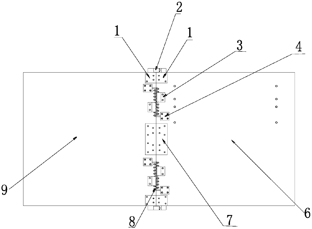
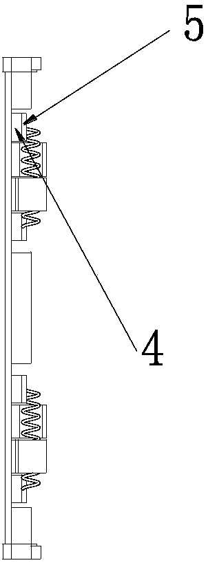
[0025] figure 1 It is a schematic diagram of the fully deployed state of the solar wing, and the battery is pasted on the opposite side of this side. figure 2 It is a side view of the solar wing deployment and locking mechanism of the present invention after the solar wing is deployed.

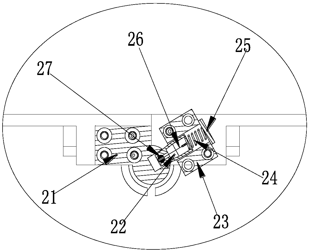
[0026] The spring-driven solar wing deployment and locking mechanism of the present invention includes an end rotating seat 1, an intermediate rotating seat 7, a torsion spring limiting seat 3, a torsion spring compression seat 4, a torsion spring compression cover plate 5, a fixed Sun wing 6, unfolded sun wing 9, aramid fiber thread 10, special adhesive tape 11 and locking mechanism 2. The driving torque of the deployable solar wing is provided by the potential energy of the spring when it is twisted. After the deployment is in place, the locking mechanism ...


PUM


Abstract

The invention provides a solar wing unfolding and locking mechanism based on spring drive. The mechanism comprises torsion springs, end rotating bases, middle rotating bases, torsion spring limiting bases, torsion spring compacting bases, torsion spring compacting cover plates, aramid wires, special adhesive tapes and locking mechanisms, wherein the end rotating bases are positioned at the upper and lower ends of a solar wing, are bilaterally matched through double folded solar wings, are provided with unfolding axes and binding points, and simultaneously serve as mounting planes of the locking mechanisms; the middle rotating bases are positioned at the middle part of the solar wing, are bilaterally matched through the double folded solar wings, and are provided with unfolding axes and binding points; the torsion spring compacting bases are fixed planes of straight segments at the ends of the torsion springs, and the torsion springs are compacted through the troughs of the torsion spring compacting cover plates; the torsion spring limiting bases are distributed on the double folded solar wings in a staggered mode to complete limiting of the torsion springs in a rotating process; and the driving moment obtained when the solar wing is unfolded is supplied by the potential energy obtained when the torsion springs are subjected to torsion, the solar wing is locked by the locking mechanisms after being unfolded in place, and limiting between wings and rigidity retention are realized through the aramid wires and the special adhesive tapes.

Description

technical field [0001] The invention relates to the technical field of spacecraft, in particular to a solar wing deployment and locking mechanism for aerospace. Background technique [0002] The solar wing unfolding and locking mechanism is widely used in aerospace, especially in the field of satellites. The solar wing structure mechanism is mainly used to provide an installation plane for the solar cell system and ensure the smooth deployment of the folding wing in orbit. Taking the solar wing of a satellite in the aerospace field as an example, its deployment mechanism is mainly hinge type, lotus leaf type, rotary joint, spring type, etc., and the locking mechanism mainly includes mechanical locking, friction self-locking, hinge self-stiffness locking, etc., but Existing unfolding and locking mechanisms have certain disadvantages. Among them, the hinge type often requires a certain gap between the battery panels, which occupies a large envelope space. At the same time, the...

Claims


Application Information

Patent Timeline
IPC IPC(8): B64G1/44
CPCB64G1/443
Inventor 高鸽唐心春李春马小龙陈琦
Owner AEROSPACE DONGFANGHONG DEV LTD
Why Eureka
Eureka Blog
Learn More