
Stretching mechanism-supported double-side array large-area flexible solar cell wing

A flexible solar cell and stretching mechanism technology, which is applied in the aerospace field, can solve the problems of limited deployment area and stiffness of flexible solar cell wings, poor dynamic characteristics and bearing capacity, and insufficient utilization, and achieves strong designability and power. The effect of large weight ratio and small wrapping envelope

Active Publication Date: 2020-06-09
SHANGHAI AEROSPACE SYST ENG INST
View PDF5 Cites 7 Cited by
  • Summary
  • Abstract
  • Description
  • Claims
  • Application Information

AI Technical Summary

Problems solved by technology

Japan's ADEOS-II and HIMAT satellites adopt a single-sided array flexible solar cell wing configuration, which is limited by the envelope of the folded state, and the utilization rate in the width direction is insufficient after deployment. To achieve large-area deployment, a longer stretch is required. Mechanism, dynamic characteristics and load-carrying capacity are poor
[0006] To sum up, with the rapid development of space science and technology, various high-power scientific research equipment has put forward higher and greater demands on the power of the spacecraft platform. It is difficult for traditional rigid and semi-rigid solar wings to guarantee high-power Under the circumstances, it meets the complex requirements of high stiffness, light weight, high storage ratio, etc., while the traditional flexible solar cell wings are not fully automatic deployment or the deployment area and stiffness are limited.

Method used


Image

  • Stretching mechanism-supported double-side array large-area flexible solar cell wing
  • Stretching mechanism-supported double-side array large-area flexible solar cell wing
  • Stretching mechanism-supported double-side array large-area flexible solar cell wing

Examples


Embodiment 1

[0079] Due to the space limitation of the vehicle and the large overload during the launch process, the solar wing needs to go through the process of first retracting and then unfolding. In view of the harsh space environment and the deployment requirements of tens or even hundreds of square meters, after the spacecraft is in orbit, the solar wing Wing deployment and locking are extremely important. The thinness and large size of flexible solar wings greatly increase the difficulty of designing the deployment mechanism. Traditional flexible solar cell wings often have complex mechanical structures, complex deployment processes, unstable driving processes, and easy structural vibration damage. question. Therefore, in order to meet the needs of space missions, there is an urgent need for a flexible solar wing structure that meets the requirements of large scale, high precision, high stiffness, and easy control, and supports it from the aspects of reducing structural complexity, ...

Embodiment 2

[0114] In this embodiment, in order to release the extra stress suffered by the box during the unlocking process and improve the bearing capacity, the stretching mechanism supports the large-area flexible solar battery wings of the double array and is also provided with several auxiliary sliding devices 8, and several auxiliary sliding devices 8 is installed symmetrically on the top of the stretching mechanism 2, and is connected with the upper box of the flexible solar cell array. When the constraint release mechanism of the flexible solar cell array is unlocked and released, the upper box and the lower box are separated, and the auxiliary sliding device 8 is used to release the upper box during the process of unlocking and releasing the upper box and the lower box. the force suffered.

[0115] preferred, such as Figure 18 In particular, the auxiliary sliding device 8 can be installed in the top frame structure of the stretching mechanism. Among them, such as Figure 19 ,...

Embodiment 3

[0118] In this embodiment, the upper box unfolding locking mechanism 6 is used as a passive mechanism, and the lower box unfolding locking mechanism 7 is used as an active mechanism, which together constitute an active and high-rigidity box unfolding locking mechanism. Small network, simple and reliable structure.

[0119] In terms of specific engineering realization, an optional engineering structure of the upper box body unfolding locking mechanism 6 and the lower box body unfolding locking mechanism 7 is as follows: Figure 20-21 shown.

[0120] preferred, such as Figure 20 , The upper box unfolding locking mechanism 6 may specifically include: a first body 601 , a second body 602 , a locking lever 603 , a torsion spring 604 , a rotating shaft 605 , and a limit screw 606 . Wherein, one end of the locking rod 603 is installed between the two lugs of the first body 601 through the torsion spring 604 and the rotating shaft, and the ends of the two lugs of the first body 601...


PUM

PropertyMeasurementUnit
Areaaaaaaaaaaa

Abstract

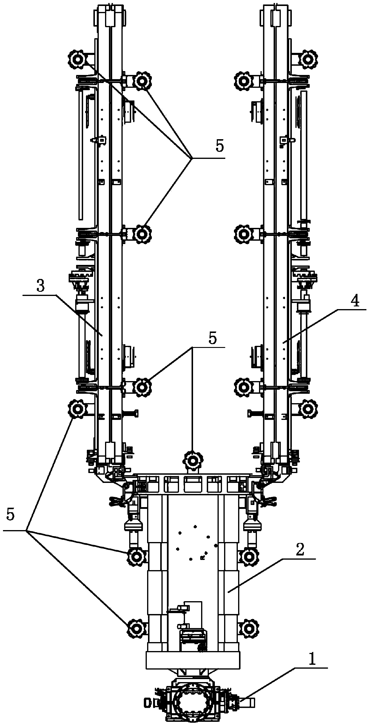
The invention discloses a stretching mechanism-supported double-side array large-area flexible solar cell wing. The stretching mechanism-supported double-side array large-area flexible solar cell wingcomprises a lifting mechanism, a stretching mechanism, two flexible solar cell arrays, pressing and releasing devices and box body unfolding and locking mechanisms; two ends of the top of the stretching mechanism are respectively connected with the two flexible solar cell arrays, and the bottom of the stretching mechanism is connected with the lifting mechanism; in an initial state, the two flexible solar cell arrays are symmetrical about the stretching mechanism; the stretching mechanism and the flexible solar cell array are each provided with a plurality of pressing points; and the pressingand release devices are arranged at the positions of the corresponding pressing points to press the stretching mechanism and the flexible solar cell arrays; the box body unfolding locking mechanismsare arranged at the connecting positions of the two ends of the top of the stretching mechanism and the first flexible solar cell array and the second flexible solar cell array and are used for unfolding the flexible solar cell arrays towards two sides in place and locking the flexible solar cell arrays. The stretching mechanism-supported double-side array large-area flexible solar cell wing has the advantages of small folding envelope, large unfolding area and stable unfolding configuration, and is suitable for a high-power spacecraft platform.

Description

technical field [0001] The invention belongs to the field of aerospace technology, in particular to a large-area flexible solar battery wing supported by a stretching mechanism for a double-sided array. Background technique [0002] With the development of my country's aerospace technology, the power demand of spacecraft is increasing rapidly. For example, communication satellites, electronic reconnaissance satellites, etc. require more than 10kW of power generation power, large space-based radar satellites, and deep space exploration electric propulsion satellites require as much as 40kW of electric energy, and my country's future space station power requirements even reach the order of hundreds of kilowatts. [0003] Taking a certain type of space station in the future as an example, the three cabins (core cabin, experimental cabin I and experimental cabin II) of this certain type of space station need to be used together with multiple sets of solar battery wings, and mult...

Claims


Application Information

Patent Timeline
IPC IPC(8): H02S30/20H02S30/10H02S20/30
CPCH02S20/30H02S30/10H02S30/20Y02E10/50
Inventor 何文松罗斌施飞舟王治易咸奎成程雷崔琦峰张雷马季军付清山倪啸枫霍杰彭志龙许文彬殷爱平宋佳蒋秋香王威袁伟郑宗勇汤亮顾珏华
Owner SHANGHAI AEROSPACE SYST ENG INST
Learn More