Eureka AIR delivers breakthrough ideas for toughest innovation challenges, trusted by R&D personnel around the world.

Cone expanding collapsible medical device

a medical device and collapsible technology, applied in the field of collapsible medical devices, can solve the problems of high reliability once successfully deployed, and achieve the effect of reducing the thickness of the device and optimising its compressibility

Active Publication Date: 2016-07-21
COOK MEDICAL TECH LLC
View PDF10 Cites 7 Cited by
  • Summary
  • Abstract
  • Description
  • Claims
  • Application Information

AI Technical Summary

Benefits of technology

The patent describes a medical device that can be used to treat blockages in blood vessels. The device has a conical structure that is designed to fit snugly against the vessel wall and can be compressed to a small size for deployment in small vessels. The conical membranes are self-supporting, meaning they do not require a supporting structure, and are made of a flexible material called silicone. The device can also have additional frame elements that extend beyond the conical members, which can be embedded in the membrane to secure the device in place and reduce its thickness. Overall, the device provides a reliable and flexible solution for treating blockages in blood vessels.

Problems solved by technology

While these latter occluders take time to achieve occlusion, they tend to have high reliability once successfully deployed.

Method used


Image

  • Cone expanding collapsible medical device
  • Cone expanding collapsible medical device
  • Cone expanding collapsible medical device

Examples


Embodiment Construction

[0031]The skilled person will appreciate that the drawings are schematic only and simplified in order to depict the principal elements of the devices shown. The elements shown in the drawings are also not to scale. Suitable sizing and scaling will be readily determinable by the skilled person having regard to common knowledge in the art.

[0032]The preferred embodiments described below and shown in the drawings are related to an occluder device for occluding a body vessel. The teachings herein are not, however, limited to occlusion devices as they could equally be applied to other devices. For example, the conical members could be made porous or with apertures allowing the passage of blood plasma but which are small enough to trap debris such as thrombi formations, thereby to act as filtering elements. The teachings herein are therefore applicable to a variety of implantable medical devices.

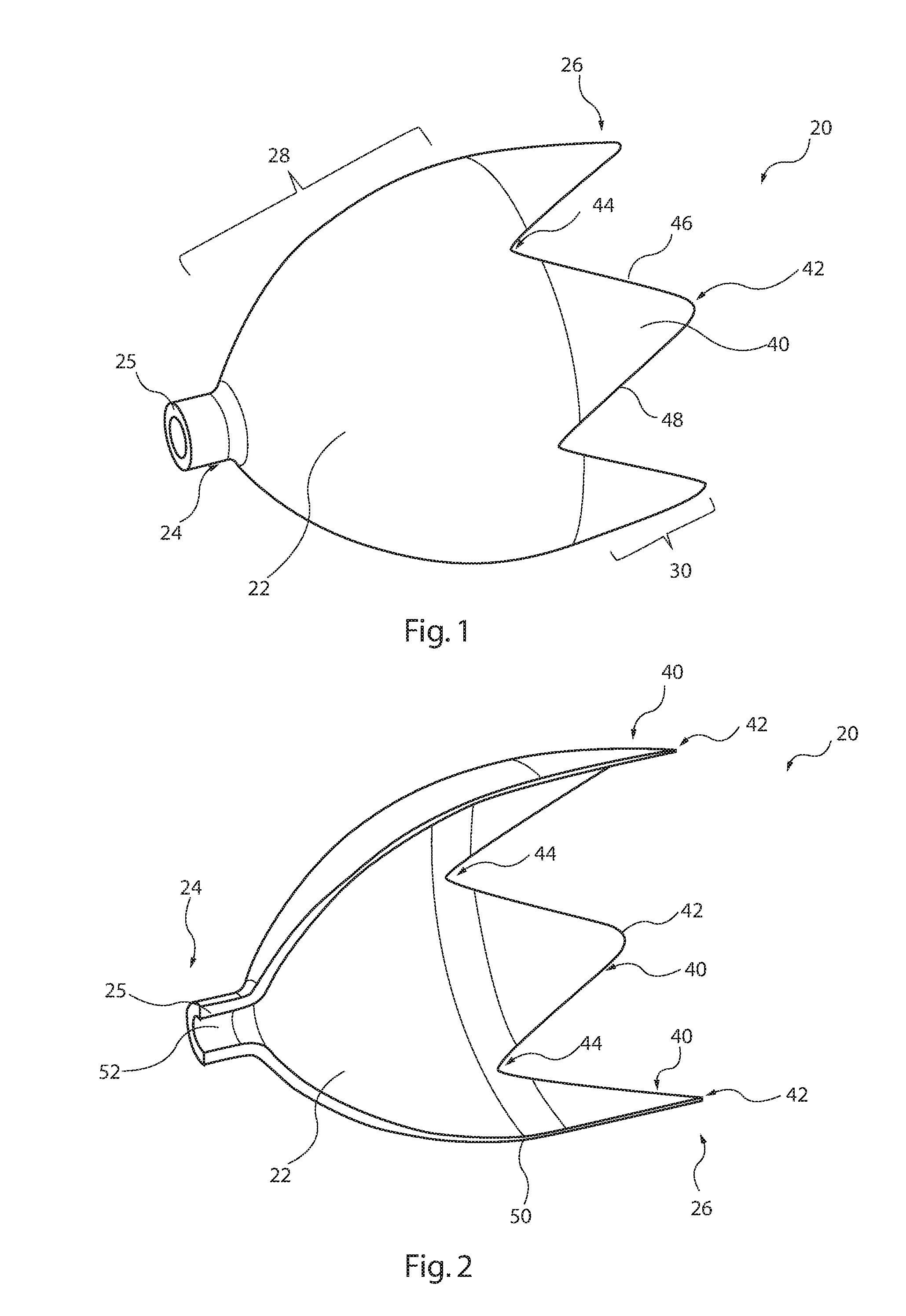
[0033]Referring first to FIG. 1, this shows in schematic form an embodiment of conical member 2...


PUM


Abstract

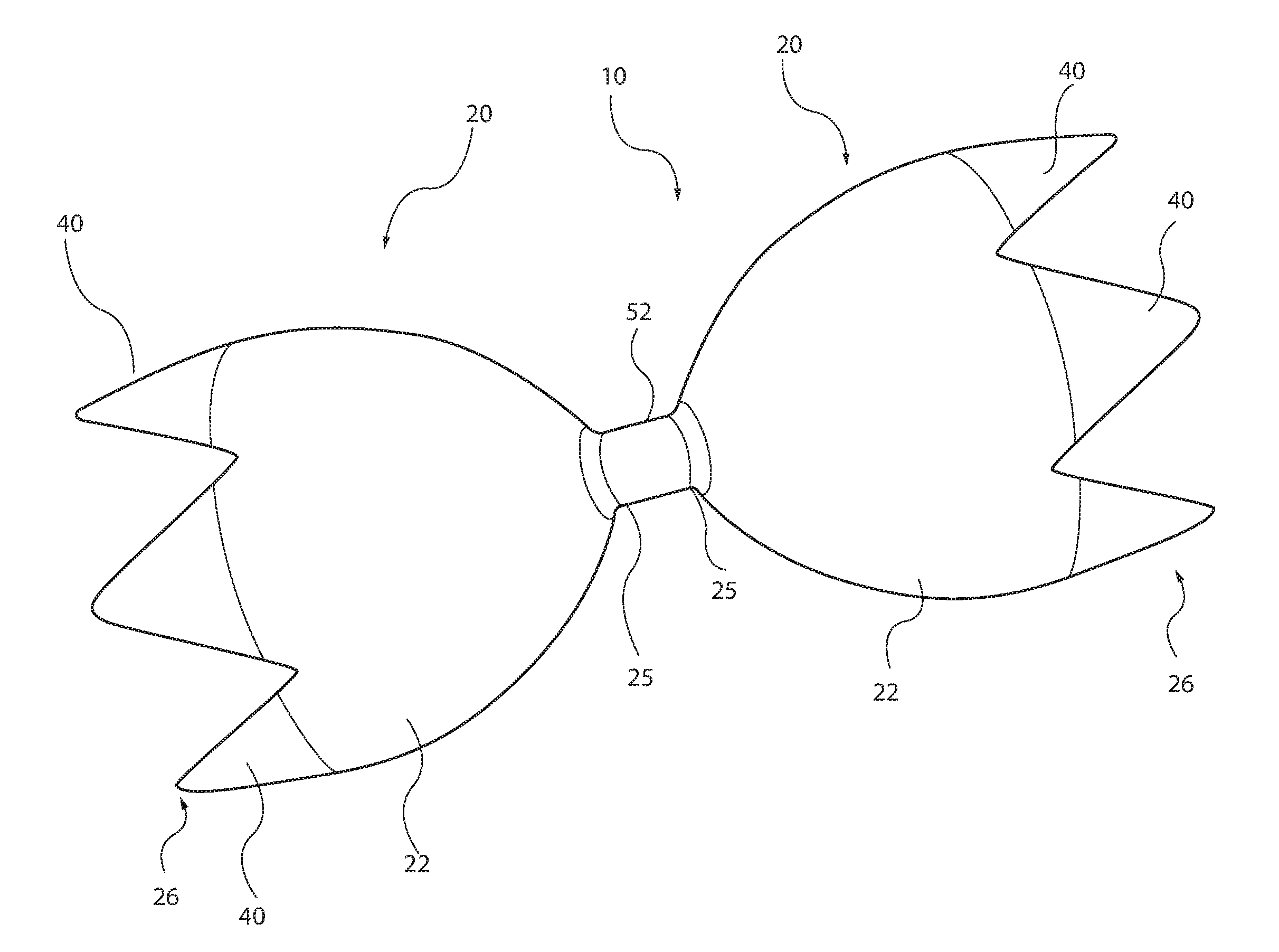
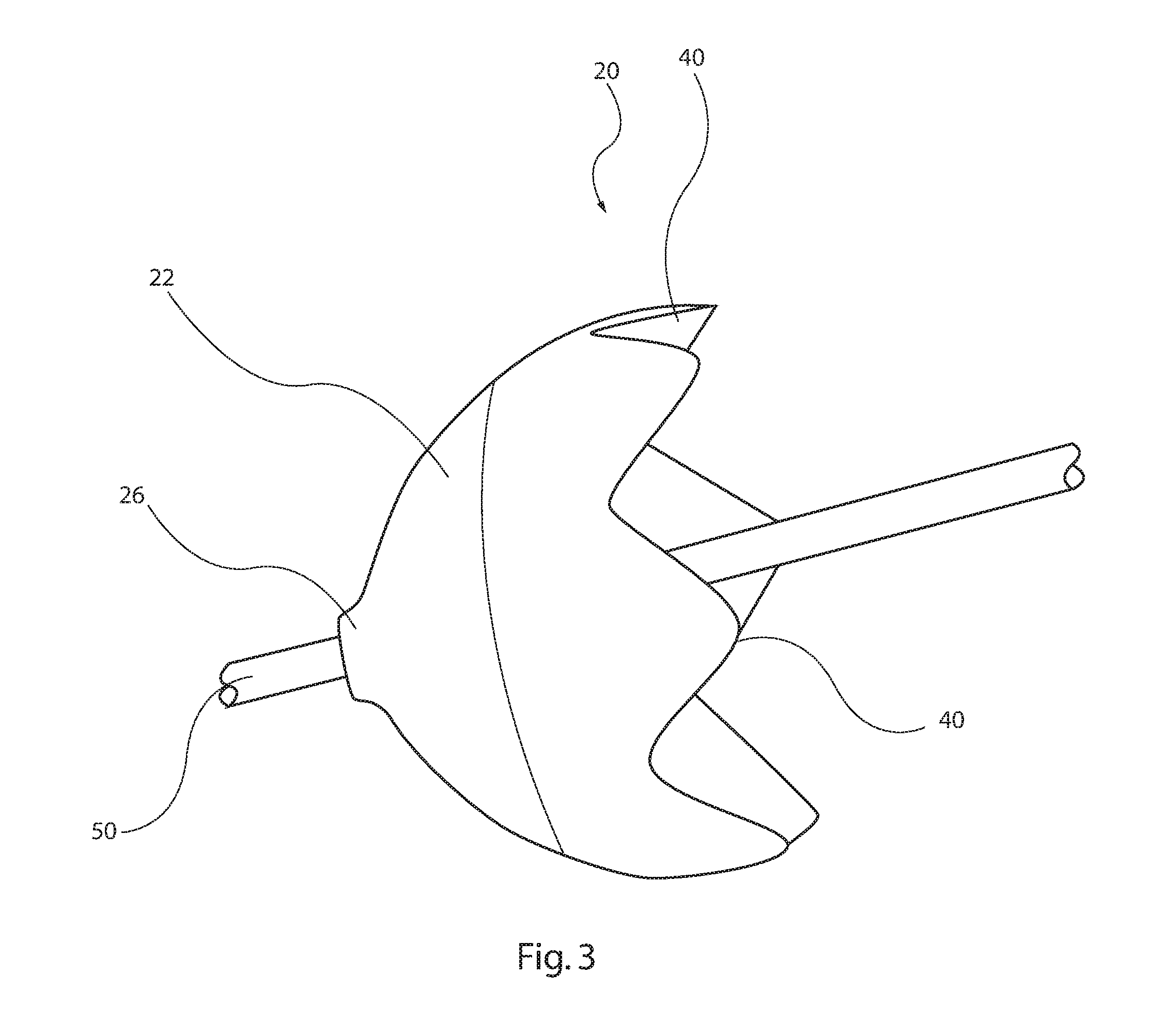
A vascular occluder includes first and second conical members disposed in opposing relation and which have tooth-shaped wide ends. The conical members are coupled to one another by a coupling element, which may be a cannula or rod. The conical members are formed of a membrane which has a thickness which increases towards the narrow ends and decreases towards the toothed elements. The toothed elements are preferably self-supporting within a vessel and avoid folds within the occluder membrane, which may otherwise result in leakage of blood around the device. The device may be provided with a supporting frame which may be at least partially embedded within the membrane. The membrane is preferably made of silicone.

Description

RELATED APPLICATIONS[0001]This application claims the benefit of priority under 35 U.S.C. §119(a) to Great Britain Patent Application No. GB 1500735.4, filed on Jan. 16, 2015, which is incorporated by reference here in its entirety.TECHNICAL FIELD[0002]The present invention relates to a collapsible medical device for vascular implantation, in the preferred embodiment to a vascular occluder.BACKGROUND ART[0003]There is a plurality of medical conditions for which it is desired to occlude a body vessel, be it temporarily or permanently. Occlusion devices for this purpose could be categorized into two different types, a first which provides instant occlusion of a vessel and a second which relies on embolization. Instant occluders provide a physical barrier spanning across the diameter of the vessel and can achieve near instantaneous occlusion. Such devices, however, must remain reliably in place without migration or leakage through the occluder, between the occluder and the vessel wall....

Claims


Application Information

Patent Timeline
Patent Type & Authority Applications(United States)
IPC IPC(8): A61B17/12
CPCA61B17/12109A61B2017/00477A61B17/12172A61B17/12045A61B17/12031A61B17/12177A61B2017/12054A61F2002/016A61F2230/008A61F2/0105A61B17/12022
Inventor BODEWADT, TUE THURENHANSEN, CHRISTINA RAUFF
Owner COOK MEDICAL TECH LLC
Why Eureka
Eureka Blog
Learn More