
System and process for controlling the coding bit rate of streaming media data employing a limited number of supported coding bit rates

a streaming media and coding bit rate technology, applied in the field of controlling the coding bit rate of streaming media, can solve the problem of startup delay remaining, achieve the effect of maximizing the quality of playback of data, smoothing the average coding bit rate over consecutive periods, and improving stability

Inactive Publication Date: 2009-05-19
MICROSOFT TECH LICENSING LLC
View PDF22 Cites 82 Cited by
  • Summary
  • Abstract
  • Description
  • Claims
  • Application Information

AI Technical Summary

Benefits of technology

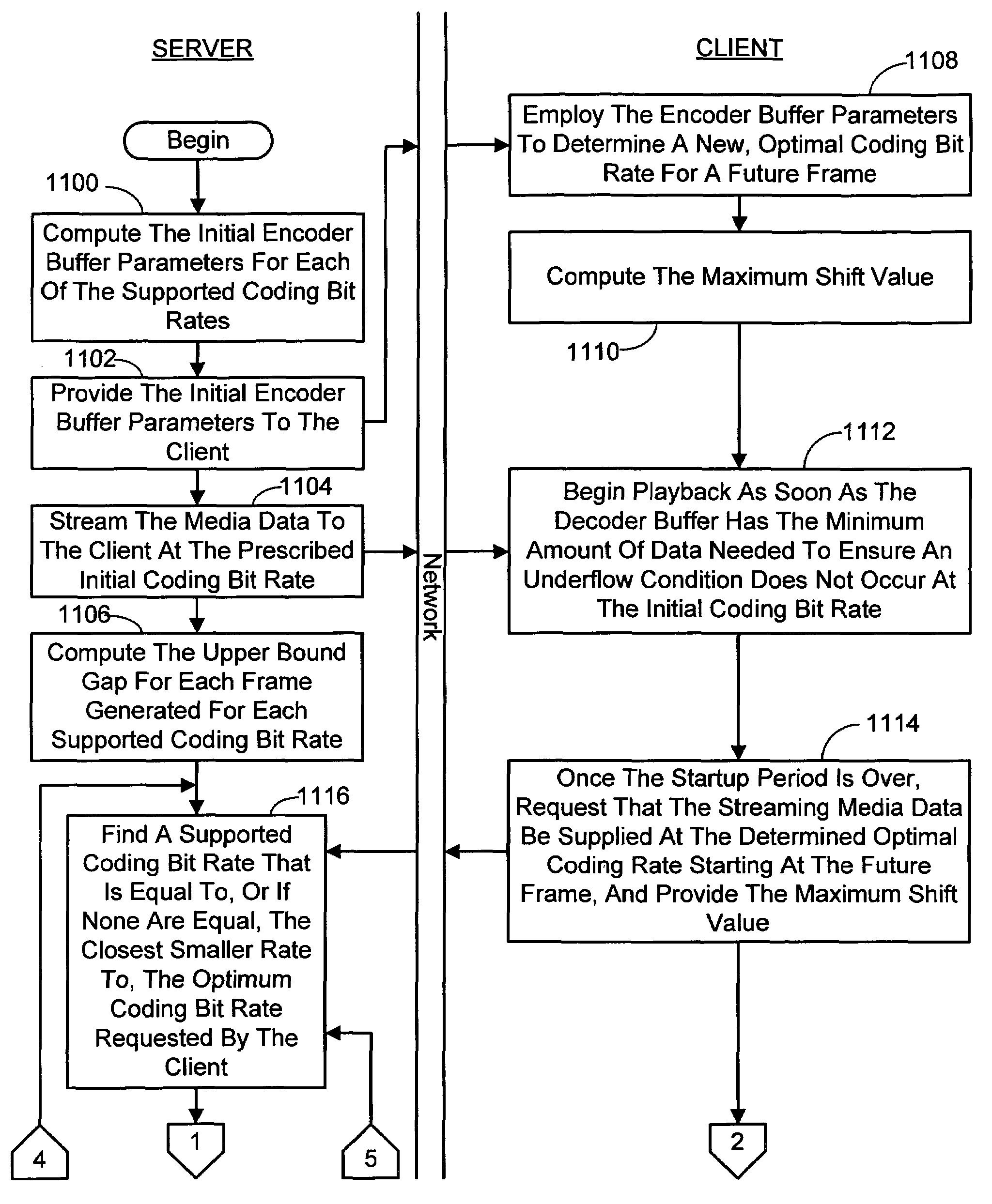
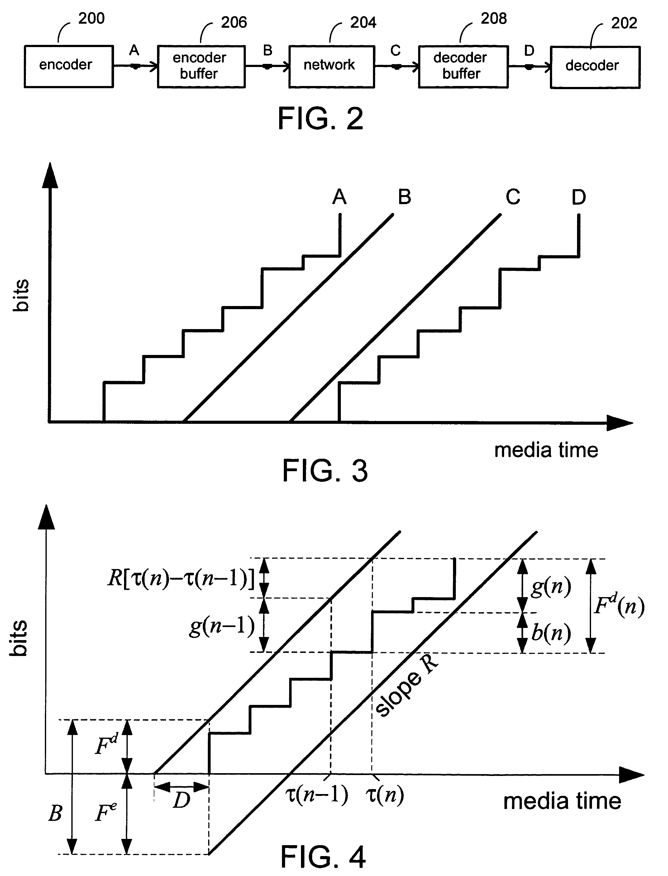
[0019]The present invention is directed toward a system and process for controlling a coding bit rate of streaming media data being transmitted to a client from a server over a computer network. In general, this coding bit rate control involves dynamically adjusting the coding bit rate of the streaming media data to control the client buffer duration. The purpose of this is to prevent the client buffer from underflowing, while keeping the average coding bit rate close to the average transmission bit rate of the network (an thus maximizing the quality of the playback of the data). The problem of coding bit rate control is formulated as a standard problem in linear quadratic optimal control, in which the client buffer duration is controlled as closely as possible to a target level. The smoothness of the average coding bit rate over consecutive frames is also considered when deciding whether to change the coding bit rate as part of the optimal control process. This yields a higher and more stable quality as network conditions change. In addition, the natural variation in the instantaneous coding bit rate that occurs for a given average coding bit rate is explicitly take into consideration. This is accomplished by incorporating the leaky bucket model into the control loop so that the changes in buffer duration due to natural variation in the instantaneous coding bit rate are not mistaken for changes in buffer duration due to network congestion. It is noted that in the present system and process, it is not the actual fullness of the client buffer that is controlled, but an upper bound on the time of arrival of bits into the client buffer, to a target level. The upper bound is based on the leaky bucket model of the coding bit rate.
[0020]Preventing the client buffer from underflowing, while keeping the average coding bit rate close to the average transmission bit rate of the network, meets two of the aforementioned user expectations. Namely, if the buffer never underflows, it allows for continuous playback. In addition, keeping the average coding bit rate close to the average transmission bit rate of the network means the data is played back with the highest possible quality given the average communication bandwidth available. This leaves the remaining issue of startup delay. This issue is resolved in the present system and process by controlling the size of the client buffer over time. More particularly, the aforementioned client buffer target level is adjusted to start small, and then grow slowly over time. If the buffer is initially small, it allows for shorter startup delay. In addition, as the buffer is eventually allowed to grow large, it enhances the robustness of the system as well as creating high, nearly constant quality. Thus, client buffer management is a key element affecting the performance of streaming media systems.
[0026]When a frame with a new average coding bit rate arrives at the client there is a shift in the upper bound gap. This shift can be on the order of seconds and hence, rather than being negligible, can be confusing to the controller. One solution to this is to introduce a simultaneous shift in the control target schedule. To this end, the server also computes a shift value for each frame representing the first frame after a coding bit rate change. This shift value represents the difference between the upper bound gap that would be associated with the frame generated immediately before this first frame had it been encoded at the new coding bit rate and the upper bound gap actually associated with the frame as encoded at the previous coding bit rate. The shift value is provided to the client along with the first frame after a change in the coding bit rate. The client shifts the currently scheduled target arrival time associated with the just received “first” frame by the shift value provided, and the currently scheduled target arrival times for future frames are shifted such that they collectively approach, over a period of time, and eventually coincide with, the previous target arrival times for those frames. In this way the adverse effects of an upper bound gap shift when the coding bit rate is changed are mitigated and the target arrival time values are eventually brought back in line.
[0027]In regard to the target arrival time for each frame, these are chosen so as to make the amount of time between the target time of a frame and its playback time large enough, after the startup period, that network jitter, delays and throughput changes which may cause the actual arrival time of the frame to be after its target arrival time do not result in the frame arriving after its scheduled playback time. During the startup period, the target arrival times are chosen so as to make the target arrival time closer to the playback time to assist in reducing startup delay. In one embodiment this is accomplished by setting the target arrival time for each frame using a logarithmic target schedule. In another embodiment this is accomplished by setting the target arrival time for each frame using a two-piece linear target schedule where the difference between the target arrival time and the playback time for a frame arriving during the startup period increases linearly to a prescribed amount of time that is large enough to account for the network jitter, delays and throughput changes and after which the difference remains substantially constant.
[0029]In regard to the client identifying the coding bit rate for each frame that also reduces the change in the coding bit rate to a prescribed degree, it is noted that the prescribed degree can vary depending on whether the coding bit rate increased. If it did increase, then the prescribed degree to which any future change in the coding bit rate is minimized is made greater in comparison to the prescribed degree in cases where the last change in the coding bit rate decreased the rate. Still further, it is also desirable to minimize quality variations due to large or frequent changes to the coding bit rate. In order to stabilize the code bit rate changes, the following actions can be taken. First, in the case where the client identifies a new coding bit rate that represents an increase, a new coding bit rate would be requested from the server only if the new rate does not exceed the current moving average arrival rate of the frames. In another embodiment, the new coding bit rate representing an increase would only be requested from the server, even if it exceeds the current moving average arrival rate of the frames, if the current client buffer duration exceeds the desired duration level by an amount that it is estimated will not be expended at the higher coding bit rate prior to the passing of a prescribed period of time (e.g., 60 seconds). However, in a case where the client identifies a new coding bit rate that represents a decrease, a new coding bit rate would be requested from the server even if it represents a significant departure from the immediately previous coding bit rate. This is because there is little risk in the client buffer underflowing when the coding rate is decreased.

Problems solved by technology

This leaves the remaining issue of startup delay.

Method used


Image

  • System and process for controlling the coding bit rate of streaming media data employing a limited number of supported coding bit rates
  • System and process for controlling the coding bit rate of streaming media data employing a limited number of supported coding bit rates
  • System and process for controlling the coding bit rate of streaming media data employing a limited number of supported coding bit rates

Examples


Embodiment Construction

[0050]In the following description of the preferred embodiments of the present invention, reference is made to the accompanying drawings which form a part hereof, and in which is shown by way of illustration specific embodiments in which the invention may be practiced. It is understood that other embodiments may be utilized and structural changes may be made without departing from the scope of the present invention.

I. The Computing Environment

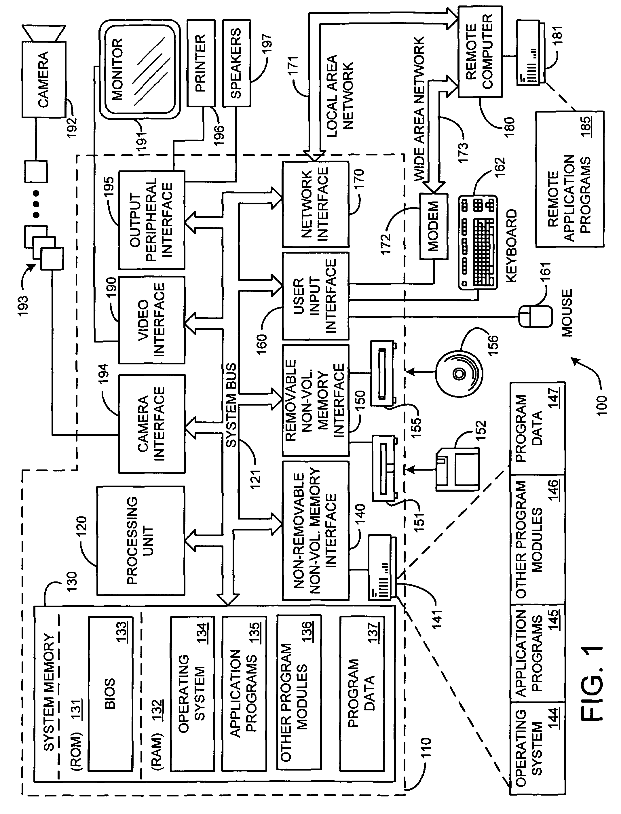
[0051]Before providing a description of the preferred embodiments of the present invention, a brief, general description of a suitable computing environment in which portions of the invention may be implemented will be described. FIG. 1 illustrates an example of a suitable computing system environment 100. The computing system environment 100 is only one example of a suitable computing environment and is not intended to suggest any limitation as to the scope of use or functionality of the invention. Neither should the computing environment 100 ...


PUM


Abstract

A system and process for controlling the coding bit rate of streaming media data is presented where a server streams data that exhibits one of a number of coding bit rates supported by the server. Initially, the server chooses the coding bit rate. However, after this startup period, the client provides coding bit rate requests. The server transmits the streaming media data at the most appropriate supported coding bit rate closest to the rate requested. The coding bit rates requested are those estimated to provide a high quality playback of the streaming data while still keeping a decoder buffer of the client filled to a desired level. A leaky bucket model is incorporated so that the changes in buffer duration due to natural variation in the instantaneous coding bit rate are not mistaken for changes in buffer duration due to network congestion.

Description

BACKGROUND[0001]1. Technical Field[0002]The invention is related to controlling the coding bit rate of streaming media, and more particularly to a system and process for controlling the coding bit rate of streaming media data that provides fast startup, continuous playback, and maximal quality and smoothness over the entire streaming session.[0003]2. Background Art[0004]Perhaps the major technical problem in streaming media on demand over the Internet is the need to adapt to changing network conditions. As competing communication processes begin and end, the available bandwidth, packet loss and packet delay all fluctuate. Network outages lasting many seconds can and do occur. Resource reservation and quality of service support can help, but even they cannot guarantee that network resources will be stable. If the network path contains a wireless link, for example, its capacity may be occasionally reduced by interference. Thus it is necessary for commercial-grade streaming media syste...

Claims


Application Information

Patent Timeline
Patent Type & Authority Patents(United States)
IPC IPC(8): G06F15/16
CPCH04N21/23406H04N21/2402H04N21/44004H04N21/44245H04N21/6373H04N21/643
Inventor CHOU, PHILIPKLEMETS, ANDERSHUANG, CHENG
Owner MICROSOFT TECH LICENSING LLC
Learn More