Receiver-driven layered error correction multicast over heterogeneous packet networks

a packet network and multicast technology, applied in data switching networks, instruments, coding, etc., can solve the problems of inability to receive the highest quality transmission, inability to meet the requirements of the transmission rate, so as to achieve the effect of maximizing the quality of the transmission ra

Inactive Publication Date: 2005-11-10
ROVI TECH CORP
View PDF8 Cites 29 Cited by
  • Summary
  • Abstract
  • Description
  • Claims
  • Application Information

AI Technical Summary

Benefits of technology

[0016] However, in regard to the error correction layers, while it would be possible to use any currently existing error correction technique appropriate for packetized audio and video signals, or combination thereof, it is preferred that a specific error correction method be employed. This method is a unique adaptation of an existing process known as Forward Error Correction (FEC). In essence, the FEC technique involves encoding the transmission data using a linear transform which adds redundant elements. The redundancy permits losses to be corrected because any of the original data elements can be derived from the encoded elements. Thus, as long as enough of the encoded data elements are received so as to equal the number of the original data elements, it is possible to derive all the original elements. Specifically, the FEC technique is adapted to the present invention by producing parity layers that go along with each source layer. To form the parity layers, the packets in a source layer are partitioned into k packets per block, forming for each block a k by m matrix of bytes, X. Then a systematic, rate-compatible forward error correction code is applied to each block, to produce an n by m matrix of bytes Y, which forms n−k parity packets (in addition to the original k source packets). Each of these n−k parity packets is assigned to a different parity stream or layer. Each parity layer is then transmitted in a separate stream to a different multicast group address. In this way, both the source and parity information is layered. For each source layer, there are n−k parity layers. By having many source layers, and many parity layers for each source layer, each receiver is able to independently subscribe to the optimal number of source layers, and the optimal number of parity layers for each source layer, so as to maximize quality for a given transmission rate.

Problems solved by technology

This causes the packets to reach the subscribers at some point, albeit with the inevitable packet loss due to network congestion and buffer overflow.
This heterogeneity in capacity can cause problems in the context of an Internet broadcast of real-time audio and video information.
For example, a particular receiver may not have the bandwidth available to receive the highest quality transmission that a broadcaster is capable of providing.
However, this solution was very bandwidth intensive as the same information (and more) had to be repeated in each channel.
If it subscribes to more than three layers, then congestion will certainly result and many packets will be dropped randomly, resulting in poor video quality.
However, in complex network environments such as the Internet, there is often congestion along the path between the sender and receiver that is “ambient” in the sense that it is due to cross traffic between other senders and receivers.
Therefore, it is not always possible to eliminate all congestion along the path from a sender to a receiver by cutting back on the rate of transmission between the sender and receiver, i.e., by dropping layers of the multicast.
This presents a significant problem because in RLM the receiver attempts to drop multicast groups until there is little or no loss.
However, the packet loss rate, or even the available bandwidth could fluctuate during the broadcast.

Method used


Image

  • Receiver-driven layered error correction multicast over heterogeneous packet networks
  • Receiver-driven layered error correction multicast over heterogeneous packet networks
  • Receiver-driven layered error correction multicast over heterogeneous packet networks

Examples


Embodiment Construction

[0032] In the following description of the preferred embodiments of the present invention, reference is made to the accompanying drawings which form a part hereof, and in which is shown by way of illustration specific embodiments in which the invention may be practiced. It is understood that other embodiments may be utilized and structural changes may be made without departing from the scope of the present invention.

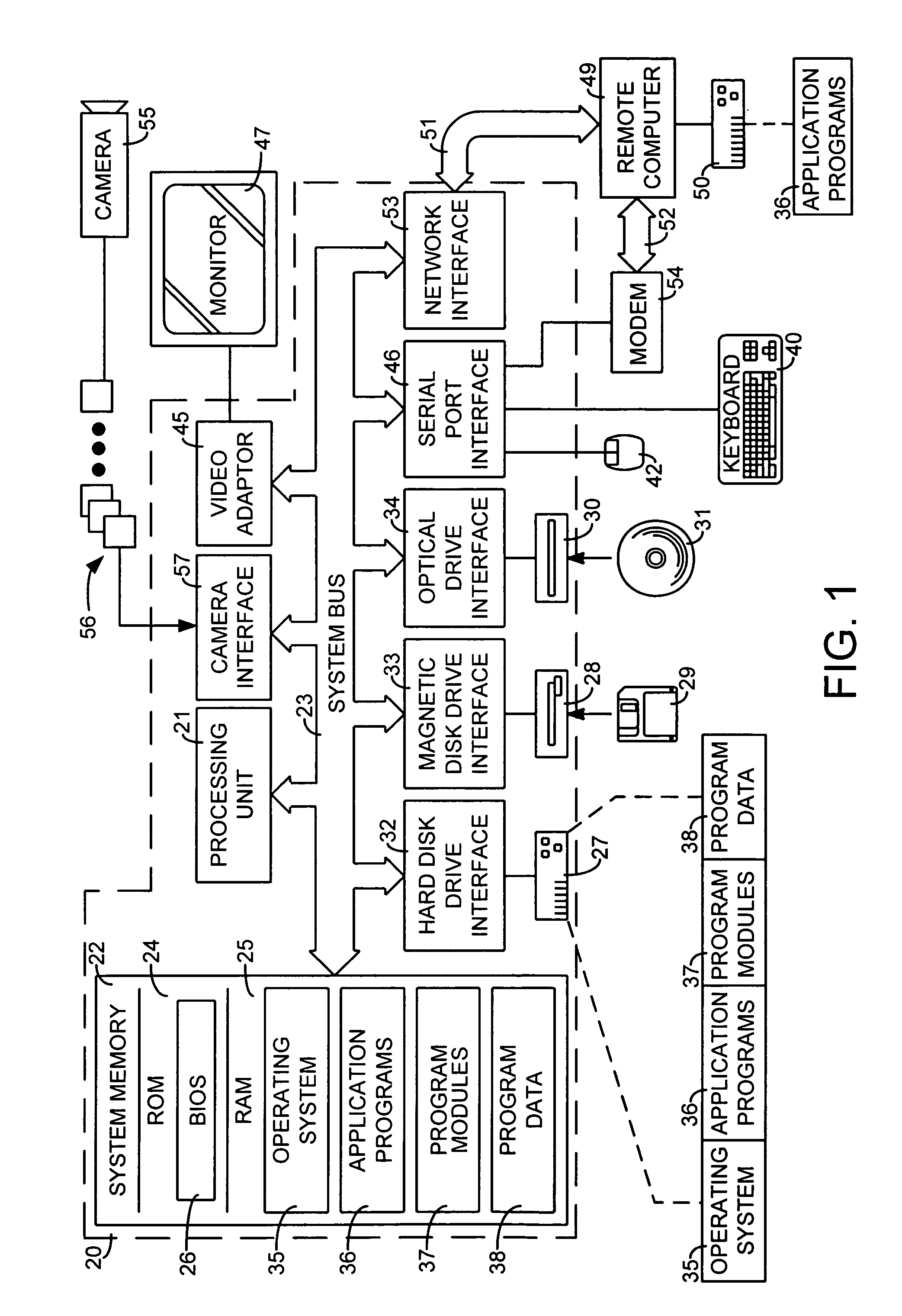
[0033]FIG. 1 and the following discussion are intended to provide a brief, general description of a suitable computing environment in which the invention may be implemented. Although not required, the invention will be described in the general context of computer-executable instructions, such as program modules, being executed by a personal computer. Generally, program modules include routines, programs, objects, components, data structures, etc. that perform particular tasks or implement particular abstract data types. Moreover, those skilled in the art will appreciate...


PUM


Abstract

A system and method for correcting errors and losses occurring during a receiver-driven layered multicast (RLM) of real-time media over a heterogeneous packet network such as the Internet. This is accomplished by augmenting RLM with one or more layers of error correction information. This allows each receiver to separately optimize the quality of received audio and video information by subscribing to at least one error correction layer. Ideally, each source layer in a RLM would have one or more multicasted error correction data streams (i.e., layers) associated therewith. Each of the error correction layers would contain information that can be used to replace lost packets from the associated source layer. More than one error correction layer is proposed as some of the error correction packets contained in the data stream needed to replace the packets lost in the associated source stream may themselves be lost in transmission. A preferred process for generating the error correction streams involves the use of a unique adaptation of the Forward Error Correction (FEC) techniques. This process encodes the transmission data using a linear transform which adds redundant elements. The redundancy permits losses to be corrected because any of the original data elements can be derived from any of the encoded elements. Thus, as long as enough of the encoded data elements are received so as to equal the number of the original data elements, it is possible to derive all the original elements.

Description

BACKGROUND [0001] 1. Technical Field [0002] The invention is related to a system and process for correcting errors and losses occurring during a receiver-driven layered multicast of real-time media over a heterogeneous packet network such as the Internet. [0003] 2. Background Art [0004] Real-time media, such as radio and television programs, are broadcast from a single sender to multiple, geographically distributed receivers, who have all “tuned” to that sender. Commonly, the signals are broadcast from the sender by a terrestrial antenna, but satellite and wired solutions also exist. For example, in cable TV, the signals are broadcast from a sender by propagating a voltage along a coaxial cable to receivers connected to the cable. [0005] It is also possible to use the Internet infrastructure to broadcast audio and video information. This is typically accomplished using the Internet Protocol (IP) Multicast mechanism and its associated protocols. An Internet broadcast (or more properl...

Claims


Application Information

Patent Timeline
Patent Type & Authority Applications(United States)
IPC IPC(8): H04L1/00H04L1/06H04L1/08
CPCH04L1/0009H04L1/0017H04L2001/0093H04L1/06H04L1/1812H04L1/007
Inventor CHOU, PHILIP A.WANG, ALBERT S.MEHROTRA, SANJEEVMOHR, ALEXANDER E.
Owner ROVI TECH CORP
Why Eureka
Try Eureka