
Adaptation of a directional characteristic of a radio signal based on the spatial orientation of a radio transmitter

a radio transmitter and spatial orientation technology, applied in the field of radio communication, can solve the problems of increasing the probability, not being able to handle a plurality of wired cable connections, and not having a sufficiently large coupling coefficient of the coil

Inactive Publication Date: 2011-01-27
NXP BV
View PDF10 Cites 29 Cited by
  • Summary
  • Abstract
  • Description
  • Claims
  • Application Information

AI Technical Summary

Benefits of technology

[0011]The described transmitter is based on the idea that the directional characteristic of a transmitted radio signal can be adjusted based on information about the spatial orientation of the transmitter and / or about the spatial orientation of the transmit coil. If the orientation of a receiver representing the recipient of the radio signal is known, the radio communication between the described transmitter and the receiver can be optimized without any feedback information about the quality of the radio link, which extends between the transmitter and the receiver. Thereby, it might be taken into account that the receiver comprises a receive coil and that the quality of the radio link respectively the quality of the radio channel between the transmitter and the receiver will be maximized if the transmit coil and the receive coil are oriented parallel with respect to each other.
[0036]According to a further aspect of the invention there is provided a communication system comprising (a) a transmitter as set forth in any one of the embodiments described above and (b) a receiver for receiving the radio signal. The described communication system is based on the idea that the directional characteristic of the transmitted radio signal can be adjusted based on orientation information about the at least on transmit coil. If the orientation of the receiver is known, the radio communication between transmitter and receiver can be optimized without any feedback information about the quality of the radio link extending between transmitter and receiver. The best radio link quality may obtained if the transmit coil and the receive coil are oriented parallel with respect to each other.

Problems solved by technology

Users are often not willing to handle a plurality of wired cable connections between different electronic products, which are placed in their close surrounding.
However, the use of only two coils increases the probability that for a certain relative orientation between the transmitter and the receiver there may be no coil having a sufficiently large coupling coefficient with the receiver coil.
However, using more than three coils typically brings only a limited added value.
The disadvantage of this scheme is that it lowers the effective link throughput by a factor of three as the same data stream has to be sent from each transmit coil sequentially.
This also increases the power consumption for the transmitter by a factor three as it needs to send the same data three times.
However, in practical circumstances there are various reasons why there may be available only an asymmetrical link or a unidirectional link between the transmitter and the receiver.

Method used


Image

  • Adaptation of a directional characteristic of a radio signal based on the spatial orientation of a radio transmitter
  • Adaptation of a directional characteristic of a radio signal based on the spatial orientation of a radio transmitter

Examples


Embodiment Construction

[0048]The illustration in the drawing is schematically.

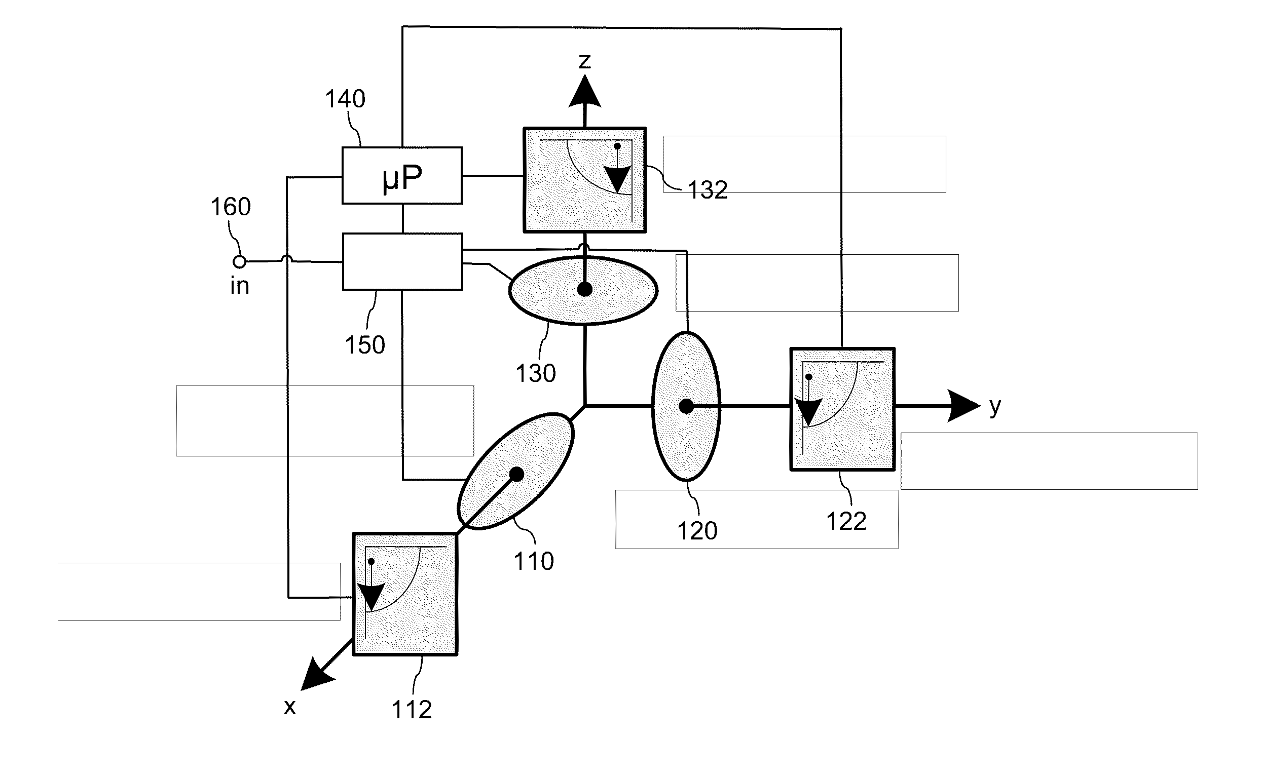
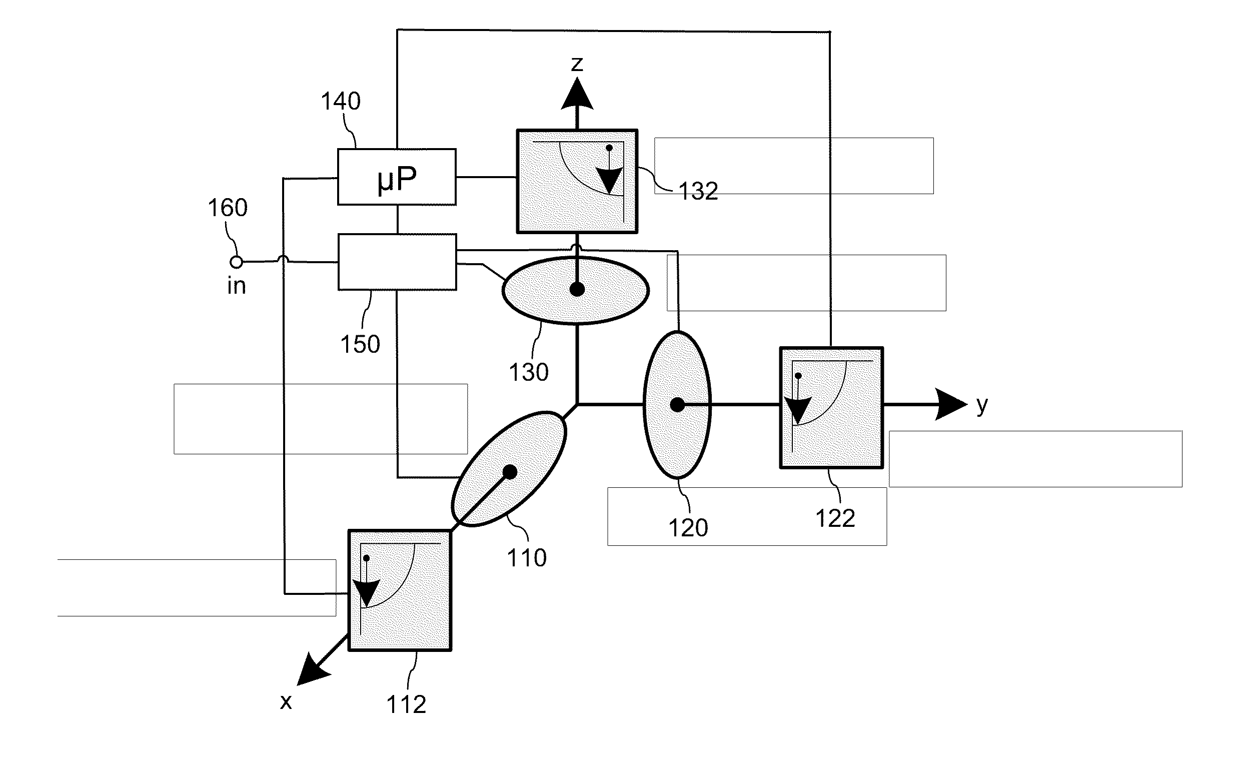
[0049]FIG. 1 shows a transmitter 100, which comprises three transmit coils. A first transmit coil 110 is aligned with an x-axis, a second transmit coil 120 is aligned with an y-axis and a third transmit coil 130 is aligned with an z-axis. Each of the transmit coils 110, 120, 130 can be activated for transmitting a radio signal from the transmitter 100 to a non depicted receiver.

[0050]The transmitter 100 further comprises three inclinometers. A first inclinometer 112 is assigned to the first coil 110 and is adapted for measuring the rotational angle of the transmitter 100 with respect to the x-axis. A second inclinometer 122 is assigned to the second coil 120 and is adapted for measuring the rotational angle of the transmitter 100 with respect to the y-axis. A third inclinometer 132 is assigned to the first coil 130 and is adapted for measuring the rotational angle of the transmitter 100 with respect to the z-axis.

[0051]The trans...


PUM


Abstract

It is described an open-loop transmit coil diversity scheme, intended for communication based on magnetic induction, wherein the diversity scheme automatically aligns the transmit coil (110) of a transmitter (100) with the receive coil of a receiver without relying on feedback information from the receiver to the transmitter (100). This may be achieved by having a plurality of coils (110, 120, 130) in the transmitter (100) and / or in the receiver. Each of these coils (110, 120, 130) may be oriented orthogonally with respect to the other coil(s). The optimal coil (130) may be selected by measuring the position angle of the transmitter (100) and / or the receiver by making use of at least one inclinometer (132). For radio communication on the transmitter and / or on the receiver this coil (130) is selected, whose orientation is maximally parallel with the orientation of the corresponding coil on the other side of the radio communication link. Alternatively, if there is only one coil in the transmitter and / or the receiver, it may be possible to spatially adjust the orientation of the transmit coil and / or the receive coil by employing at least one mechanical actuator.

Description

[0001]This application claims the priority under 35 U.S.C. §119 of European patent application no. 09166149.6, filed on Jul. 22, 2009, the contents of which are incorporated by reference herein.FIELD OF THE INVENTION[0002]The present invention generally relates to the technical field of radio communication between a radio transmitter having at least one transmit coil and a radio receiver having at least one receive coil. Specifically, the present invention relates to a transmitter for transmitting a radio signal to a receiver, wherein the transmitter comprises at least one transmit coil. The present invention relates further to a receiver for receiving a radio signal from a transmitter, wherein the receiver comprises at least one receive coil. Further, the present invention relates to a communication system, which comprises the above described transmitter and / or the above described receiver. Furthermore, the present invention relates to a corresponding radio communication method, in...

Claims


Application Information

Patent Timeline
IPC IPC(8): G01S5/04
CPCH04B5/00
Inventor THOEN, STEVEN MARK
Owner NXP BV
Learn More