Plasmonic Plate for Generating Optical Vortices

a technology of optical vortices and plasmonic plates, which is applied in the field of plasmonic plates for generating optical vortices, can solve problems such as performance drop

Active Publication Date: 2013-02-14
SELEX SISTEMI INTEGRATI
View PDF0 Cites 7 Cited by
  • Summary
  • Abstract
  • Description
  • Claims
  • Application Information

AI Technical Summary

Problems solved by technology

They are therefore subject to aging of the plastic material, which causes a drop in performance.

Method used


Image

  • Plasmonic Plate for Generating Optical Vortices
  • Plasmonic Plate for Generating Optical Vortices
  • Plasmonic Plate for Generating Optical Vortices

Examples


Embodiment Construction

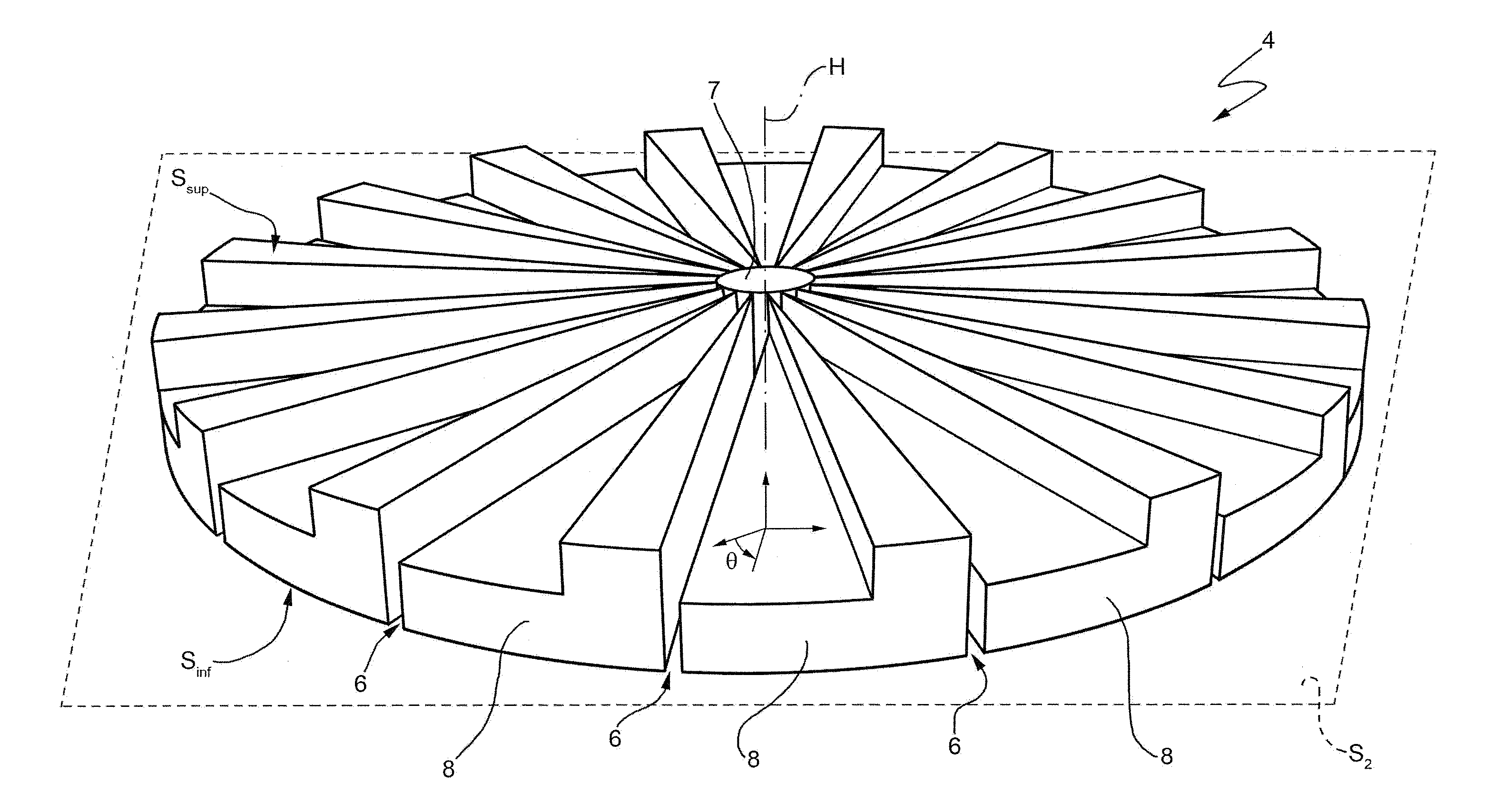
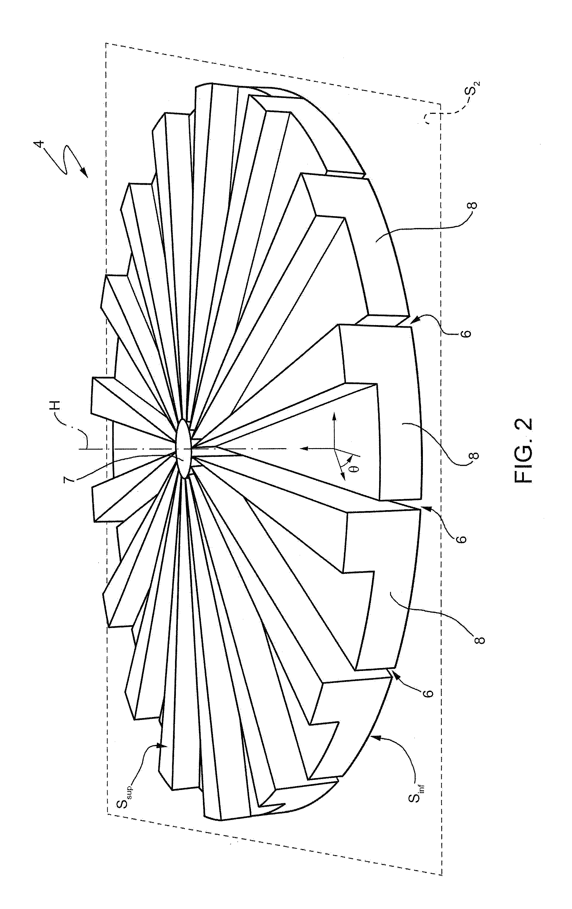
[0034]FIGS. 2 and 3 show a plasmonic plate suitable for receiving a first electromagnetic field having non-null spin angular momentum and generating, in response, a second electromagnetic field having non-null orbital angular momentum, which for brevity shall henceforth be referred to as the plate 4.

[0035]In detail, the plate 4 is made of an electrically conducting material such as, as an example, a metal (for example, silver or gold), defines a number N (for example, N=16) of slots 6 and, when viewed from above, has a circular shape.

[0036]More specifically, the plate 4 has a symmetry axis H, defines a lower plane S2, perpendicular to the symmetry axis H, and is formed by a central shield 7 and a plurality of elementary units 8 equal to one another and arranged around the central shield 7 in a non-contiguous manner, so as to define the above-mentioned slots 6, which are identical to one another, i.e. they have the same shape, as described further on.

[0037]The central shield 7 has a ...


PUM


Abstract

A plasmonic plate for generating optical vortices, formed by electrically conducting material and defining a plurality of slots that convert a first electromagnetic field having a non-null spin angular momentum into a second electromagnetic field having a non-null orbital angular momentum.

Description

BACKGROUND OF THE INVENTION[0001]As is known, given an electromagnetic field in space, the location of the points in space where the electromagnetic field has null amplitude defines a so-called phase singularity, also known as phase dislocation. By way of example, various types of phase dislocation are known, such as, for example, screw dislocation, edge dislocation or mixed screw-edge dislocation.[0002]Electromagnetic vortices, also known as so-called optical vortices, are also known. In general, the electromagnetic field defines an optical vortex when it has a dot-like phase singularity, around which the phase of the electromagnetic field itself is wrapped, creating a structure with helical phase fronts. Furthermore, the presence of one or more optical vortices is indicative of the fact that the electromagnetic field defines a location of points in space where it has null amplitude, around which the electromagnetic field assumes a circular symmetry. Therefore, in the case where it...

Claims


Application Information

Patent Timeline
Patent Type & Authority Applications(United States)
IPC IPC(8): G02B5/30
CPCG02B21/32G02B27/286G02B26/06
Inventor BOVINO, FABIO A.BRACCINI, MATTEOBENEDETTI, ALESSIO
Owner SELEX SISTEMI INTEGRATI
Why Eureka
Try Eureka