System and method for enhanced stereolithography 3D printing

a stereolithography and enhancement technology, applied in the field of systems and methods for enhancing stereolithography 3d printing, can solve the problems of imposing a cost on optical systems, imposing a physical limit to the level of miniaturization that can be achieved, and most sla 3d printers exhibit poor printing precision and accuracy

Inactive Publication Date: 2019-07-04
NUSPOT TECH LLC
View PDF0 Cites 1 Cited by
  • Summary
  • Abstract
  • Description
  • Claims
  • Application Information

AI Technical Summary

Benefits of technology

[0076]FIG. 10 is a schematic diagram illustrating the effect of the invention of using UV photons with engineered angular momentum to treat matter;
[0077]FIG. 11 is a schematic diagram illustrating the domain of application of the current innovation;
[0078]FIG. 12 is a schematic diagram illustrating the use of the innovation within a SLA 3D printer;
[0079]FIG. 13 is a schematic diagram illustrating the use of the innovation within a SLA 3D printer;
[0080]FIG. 14 is a schematic diagram illustrating the use of the innovation within a SLA 3D printer;
[0081]FIG. 15 is a schematic diagram illustrating the use of the innovation within a SLA 3D printer.

Problems solved by technology

In other words, if the irradiating wavelength is λ, then the smallest resolvable feature must be equal of greater than λ. Currently, most SLA 3D printers exhibit poor printing precision and accuracy because the prevalent use of UV Laser Diodes as a photo-polymer scriber with a cross section in the order of tens to hundreds of microns causes the photo-polymerization of clumps with dimensions of tens to hundreds of microns causing significant surface roughness.
This can impose a cost on optical systems as well as a physical limit to the level of miniaturization that can be achieved in their physical footprint.
On this front, some attempts were mainly confined to academic approaches, which were experimentally demonstrated; however, these attempts either could not be manufactured or mass produced, or generated solutions that did not provide operational scalability.
Warm-up times are therefore required, and during these times a given Hg vapor lamp will not provide an adequate UV irradiation level.
This implies that the single spectral emissions cannot be engineered to be enabled or disabled, red shift or blue shift; similarly, and most importantly the polarization of the emitted photons cannot be controlled either.
Similarly to other gas discharge lamps, the spectral emission of excimer lamps cannot be engineered to enable or disable desired wavelengths, red or blue shift, and control the polarization of the emitted photons.
However, similarly to other gas discharge lamps, the polarization of the emitted photons is not engineered.
Additionally, they typically require high power and high voltages; thus, they must use line voltage, and must be addressed as separate components that are not arbitrarily scalable.
This translates into a very inefficient use of photons, and a continuous need to generate and replace them.
This also creates a scenario where there the radiation field is not uniform.
In addition they are environmentally friendly because of the absence of Hg; however, differently from Hg vapor lamps, they enable zero-emission limitations because their on-off operation and their UV emission is pseudo-instantaneous and limited to only a few nanoseconds when supported by adequate electronic drivers.
Several impediments that stem from the Beer-Lambert Law, and the Rayleigh scattering seriously hinder the use of UV radiation for treatment of fluids.
The magnitude of the pressure exerted on a body by radiation, when the momentum carried by the former is transferred by the radiation, is relatively speaking small and therefore difficult to be observed by human beings without the aid of instrumentation.
Though this approach can potentially be extended to incorporate additional design criteria, it does usually not allow one to design a specified trade-off between resolution and power efficiency, nor the location of the undesired side lobes in the super-resolving focal plane.

Method used


Image

  • System and method for enhanced stereolithography 3D printing
  • System and method for enhanced stereolithography 3D printing
  • System and method for enhanced stereolithography 3D printing

Examples


Embodiment Construction

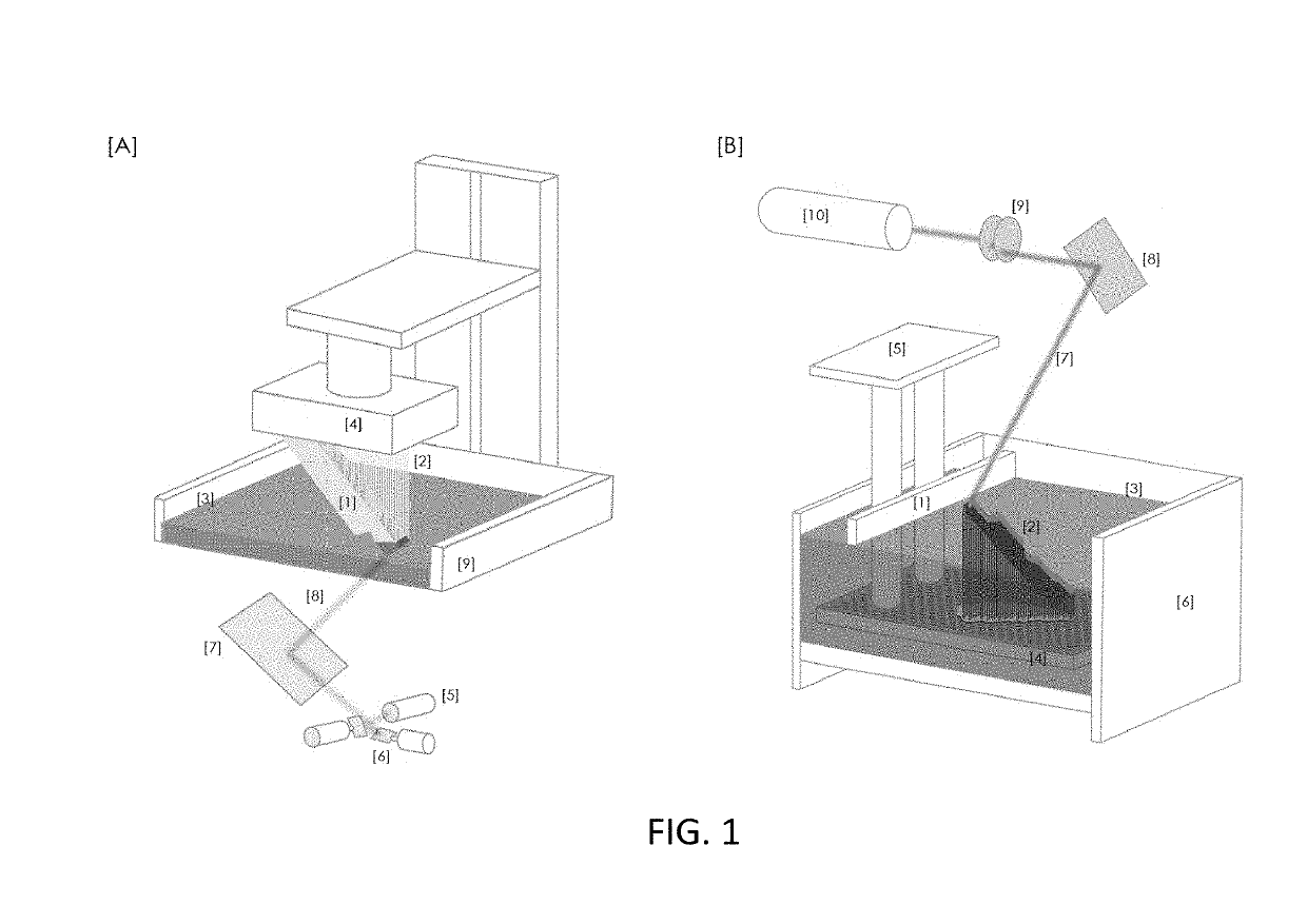
[0082]Referring now specifically to FIG. 6, one representation of the invention is an apparatus [A], [B] comprising a source of UV photons [1], one or more stand alone angular momentum generators [2] configured to deliver UV photons with optimized spin angular momentum (SAM), org orbital angular momentum (OAM), and / or a SAM / OAM [3] combination to target organic or inorganic substance and / or impurity. The angular momentum generator can have different forms [a], [b], [c], and [d].

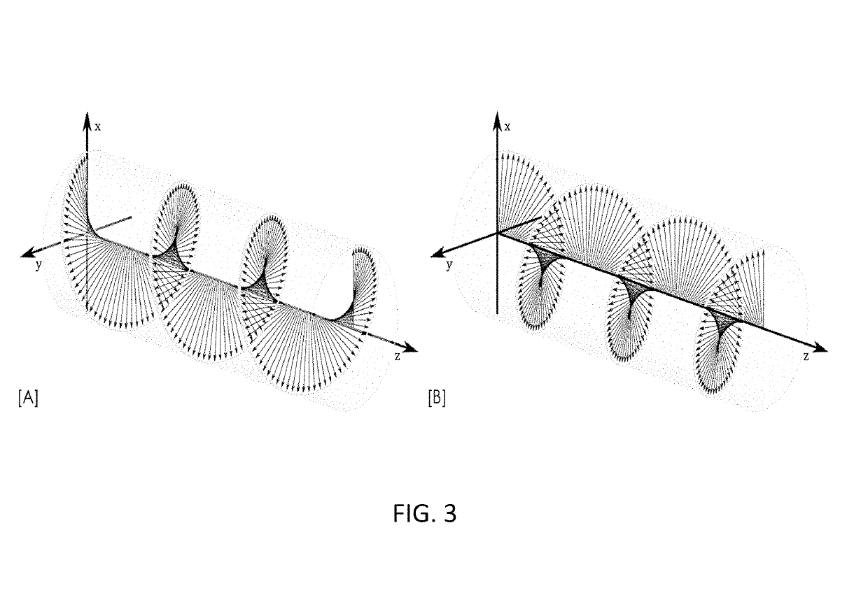
[0083]Referring now specifically to FIG. 6 [2a] UV photons can acquire optimized OAM with a Spiral Phase Plate made of UV transparent material with refractive index n, having an inhomogeneous thickness, h proportional to the azimuthal angle Φ

h=hsφ2π+h0

[0084]where hs is the step height, and h0 is the base height. When a beam of electromagnetic radiation (Gaussian) with plane phase distribution passes through this OAM generator, an optical vortex charge q is imprinted according to

q=hs(n-n0)λ

[0085]This means tha...


PUM

PropertyMeasurementUnit
fixed wavelengthaaaaaaaaaa
germicidal wavelengthaaaaaaaaaa

Abstract

A system for 3D printing utilizing near-UV and / or UV photons with engineered angular momentum, the system comprising: one of a coherent source and an incoherent source of one or more of near-UV photons and UV photons; means for obtaining one or more of super-resolved near-UV photons and super-resolved UV photons; and one or more angular momentum generators configured to impart the one or more of the near-UV photons and the UV photons with one or more of spin angular momentum (SAM) and orbital angular momentum (OAM); wherein the means for obtaining and the angular momentum generators are one or more of fabricated as stand-alone structures, fabricated on a package of the one of the coherent source and the incoherent source, and fabricated as an integral part of the one of the coherent source and the incoherent source.

Description

CROSS-REFERENCE TO RELATED APPLICATIONS[0001]The present patent application / patent claims the benefit of priority of co-pending U.S. Provisional Patent Application No. 62 / 612,771, filed on Jan. 2, 2018, and entitled “SYSTEM AND METHOD FOR ENHANCED TREATING OF MATTER WITH ENGINEERED ANGULAR MOMENTUM UV PHOTONS,” and U.S. Provisional Patent Application No. 62 / 613,794, filed on Jan. 5, 2018, and entitled “SYSTEM AND METHOD FOR ENHANCED STEREOLITHOGRAPHY 3D PRINTING,” the contents of both of which are incorporated in full by reference herein.STATEMENT OF GOVERNMENT SUPPORT[0002]The present invention was made with U.S. Government support pursuant to Award No. 140D6318C0009 by the Defense Advanced Research Projects Agency (DARPA). Accordingly, the U.S. Government may have certain rights herein.FIELD OF THE INVENTION[0003]The present invention relates generally to systems and methods for enhancing stereolithography (SLA) 3D printing by using super-resolved ultraviolet (UV) and / or near-UV r...

Claims


Application Information

Patent Timeline
Patent Type & Authority Applications(United States)
IPC IPC(8): B29C64/268B29C64/277B29C64/286B29C64/393
CPCB29C64/268B29C64/277B29C64/286B29C64/393B33Y30/00B33Y10/00B29C64/135B29C64/264G02B5/32G02B5/1838
Inventor BATONI, PAOLO
Owner NUSPOT TECH LLC
Why Eureka
Try Eureka