Photon spinning directional separator

A separator and photonic technology, applied in the direction of optical waveguide and light guide, can solve the problems of low directional separation performance and low directional separation stability, and achieve the effects of easy processing and integration, CMOS process compatibility, and high extinction ratio.

Active Publication Date: 2021-10-22
NANJING UNIV OF INFORMATION SCI & TECH
View PDF7 Cites 2 Cited by
  • Summary
  • Abstract
  • Description
  • Claims
  • Application Information

AI Technical Summary

Problems solved by technology

[0005] In order to solve the problem of low stability of metal metasurface structure in realizing directional separation, the present invention proposes a photon spin directional separator
[0006] Based on photon spin-orbit coupling and combined with the advantages of SPPs sub-wavelength regulation, the present invention provides a photon spin separation structure w

Method used


Image

  • Photon spinning directional separator
  • Photon spinning directional separator
  • Photon spinning directional separator

Examples


Embodiment 1

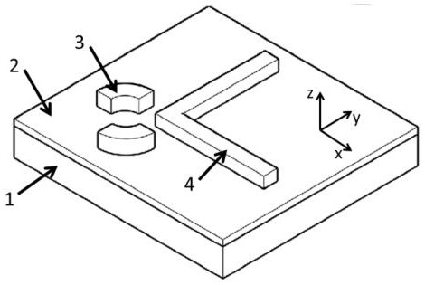
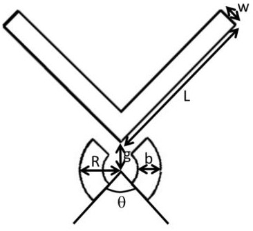
[0044] Embodiment 1, the light wave with a wavelength of 532nm is selected; the material of the substrate 1 is silicon, and the refractive index is 4.15; the material of the metal film layer 2 is silver, and the refractive index is 0.0369+i*5.4223; the antenna structure 3 and the waveguide structure 4 The material is polymethyl methacrylate PMMA, the refractive index is 1.49; the outer diameter of the double-split ring in the antenna structure 3 is R = 200nm, the width is b = 150nm, the height is h = 200nm, and the two split openings angle is = 90 o; The width of the vertical dielectric waveguide in the waveguide structure 4 is w=180nm, the height is h=200nm, and the length is L=3 microns; the distance between the center of the antenna structure 3 and the apex of the waveguide structure 4 is g=60nm;

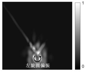
[0045] In the present invention, the antenna structure 3 supports two resonant modes with opposite resonant azimuth angles, that is, the eigenvalues ​​of the eigenequation of t...


PUM

PropertyMeasurementUnit
Heightaaaaaaaaaa
Widthaaaaaaaaaa

Abstract

The invention relates to the technical field of integrated photons, in particular to a photon spinning directional separator, and aims to solve the problem that a metal metasurface structure is low in stability of directional separation, and the photon spin directional separator comprises a substrate, a metal film layer is arranged on the substrate, and a wave guide structure is arranged on the metal film layer. The waveguide structure comprises a first dielectric waveguide and a second dielectric waveguide which are perpendicular to each other, an antenna structure is arranged on the metal film layer and comprises two sector ring structures, and the two sector ring structures are distributed on the two sides of the first dielectric waveguide and the two sides of the second dielectric waveguide at equal intervals respectively. When the spin angular momentum of the incident photon is matched with the orbital angular momentum of the antenna structure, the incident light is converted into an antenna resonant waveguide mode; meanwhile, by controlling the spinning state of incident photons, an antenna resonant waveguide mode is selectively coupled to a certain waveguide branch in the photon spin guided wave structure. The photon spinning directional separator is high in extinction ratio and integration level, and is suitable for the field of quantum communication.

Description

technical field [0001] The invention relates to the field of integrated photon design, in particular to a photon spin orientation separator. Background technique [0002] In recent years, with the progress and development of research fields such as microprocessing technology, nanomaterials, and optical field regulation, the demand for information encoding, storage rate, and device integration has increased sharply. Among them, the manipulation of photon spin states is the key to realizing on-chip communication. One of the key technologies, however, the traditional optical waveguide with dielectric as the carrier is restricted by the diffraction limit, and it is difficult to realize the sub-wavelength manipulation of photons. Therefore, how to break through the diffraction limit of light has always been the main technical bottleneck of traditional optical waveguide integration; [0003] At the same time, in recent years, the resonance technology based on surface plasmons (abb...

Claims


Application Information

Patent Timeline
IPC IPC(8): G02B6/12
CPCG02B6/12
Inventor 马佑桥李金花任海东
Owner NANJING UNIV OF INFORMATION SCI & TECH
Why Eureka
Try Eureka