
Method and apparatus for transceiving data in a wireless access system

Active Publication Date: 2013-02-14
LG ELECTRONICS INC
View PDF7 Cites 29 Cited by
  • Summary
  • Abstract
  • Description
  • Claims
  • Application Information

AI Technical Summary

Benefits of technology

[0039]According to the embodiments of the present invention, an M2M terminal can transmit/receive a signal to/from a base station or other M2M terminal according to a message including information about frame con

Problems solved by technology

Performance or capability of M2M terminals used in a cellular network is poorer than that of general terminals.
However, a scheme for transmitting/receiving data to/fr

Method used


Image

  • Method and apparatus for transceiving data in a wireless access system
  • Method and apparatus for transceiving data in a wireless access system
  • Method and apparatus for transceiving data in a wireless access system

Examples


Example

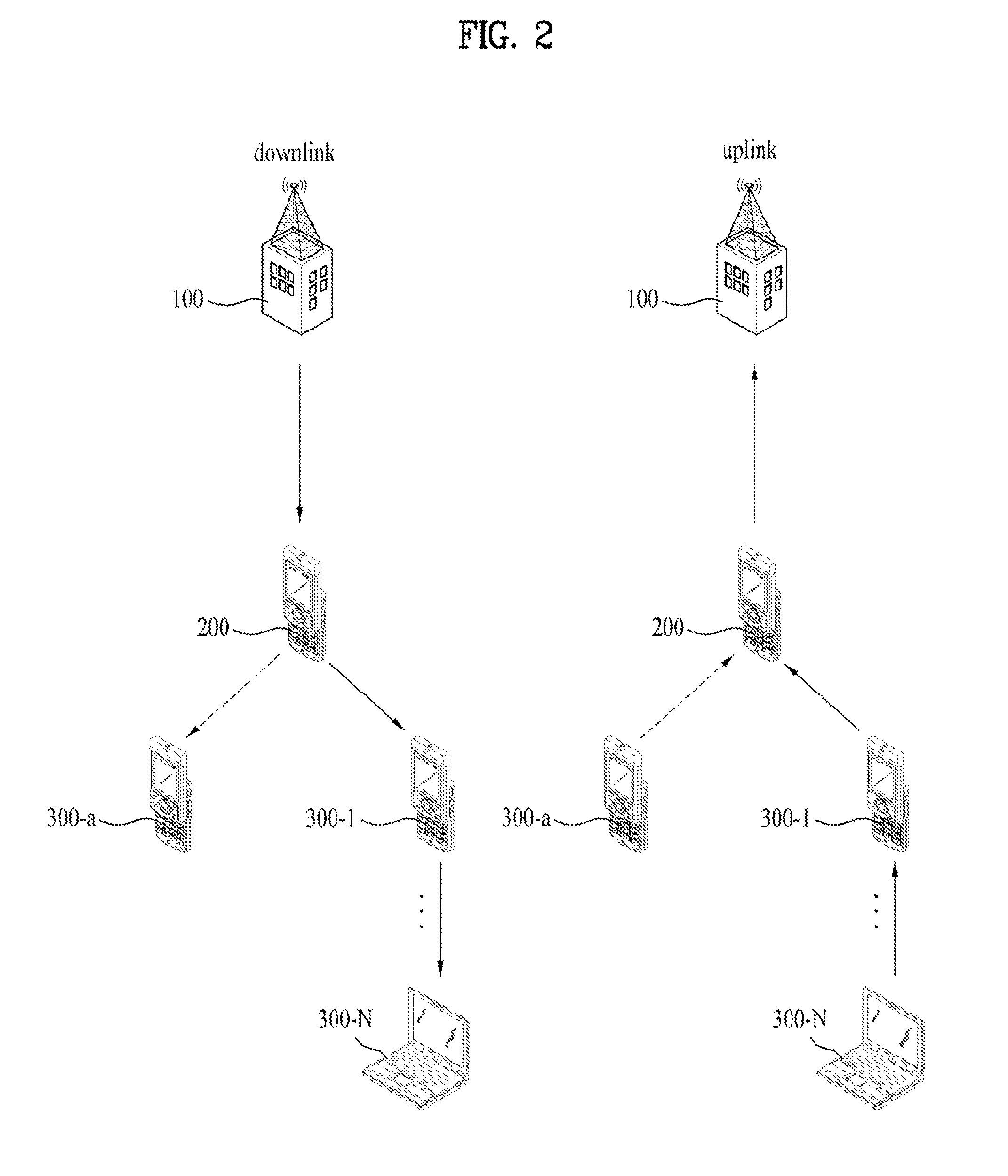
[0113]According to a second embodiment of the invention, the first terminal may receive the link transmission parameter from the base station. In this case, the first terminal can transmit the M2M relay request message to the base station (S270). The M2M relay request message may include link measurement information (channel state, CQI, SINR, interference level, path loss) received from the second terminal and information for requesting information (start time, power control, MCS, MIMO, time offset, and allocation information) related to the link transmission parameter necessary to perform M2M relay. In addition, the M2M relay request message may include channel information between the first terminal and the base station. Upon reception of the M2M relay request message, the base station determines M2M relaying transmission using the information included in the M2M relay request message and transmits the link transmission parameter to the first terminal using the M2M relay response m...


PUM


Abstract

The present invention relates to a method which involves determining a relay terminal in an M2M communication system, and transceiving data to/from a base station or other terminal through the determined relay terminal, and to a method for constructing frames for transceiving data in the M2M communication system. By means of the data-transceiving method, an M2M terminal can transmit/receive a signal to/from a base station or other M2M terminal, and frames of a base station and M2M terminal can be efficiently constructed, wherein said method includes: receiving, by a first terminal of a wireless access system, a first message including a relay operation parameter, which is information that indicates a transmitting or receiving operation, from a base station during a downlink section and/or uplink section within a frame; and transceiving, by the first terminal, data to/from the base station or other terminal on the basis of the received relay operation parameter.

Description

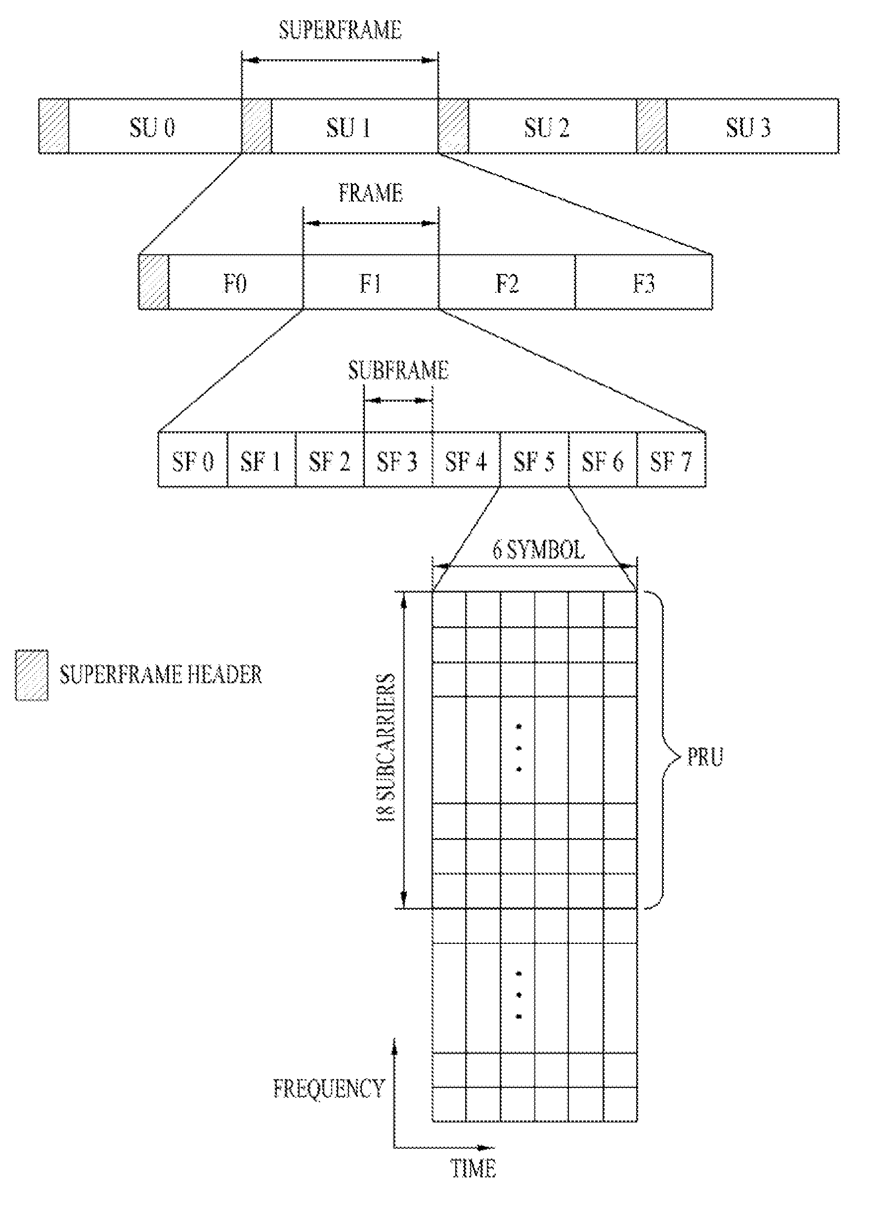
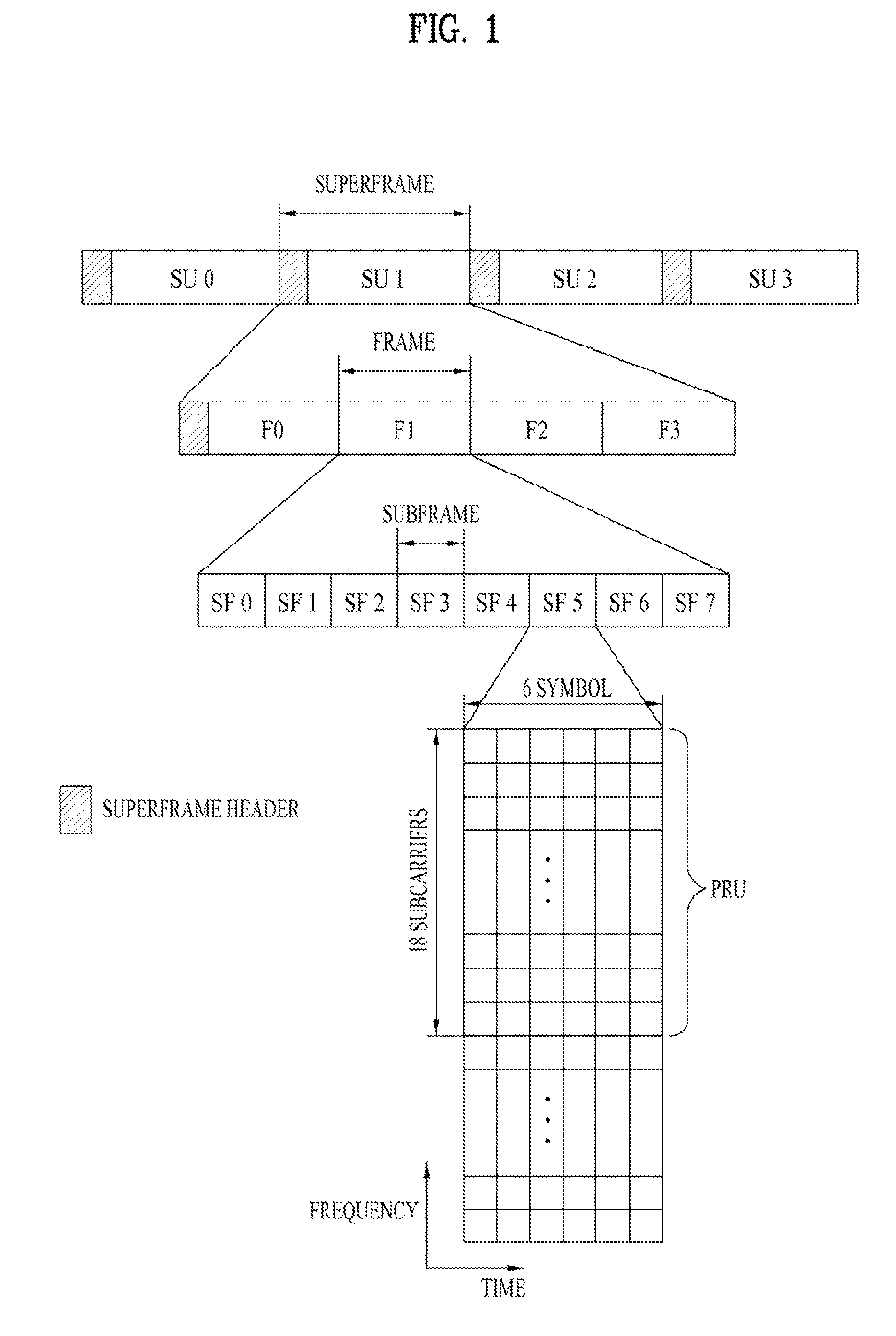
TECHNICAL FIELD[0001]The present invention relates to a wireless access system and more specifically, to a method and apparatus for transceiving data to / from a base station and other terminal in a machine-to-machine (M2M) communication system.BACKGROUND ART[0002]FIG. 1 illustrates an exemplary frame structure supported by 802.16 systems.[0003]Referring to FIG. 1, a superframe (SF) includes a superframe header (SFH) and 4 frames F0, F1, F2 and F3. The frames in the superframe may have the same duration. While each super frame is 20 ms and each frame is 5 ms in FIG. 1, the sizes of the superframe and frame are not limited thereto. The duration of a superframe, the number of frames included in a superframe, and the number of subframes included in a frame may vary. The number of subframes included in a frame may depend on channel bandwidth, the duration of a cyclic prefix (CP), etc.[0004]A frame includes a plurality of subframes SF0, SF1, SF2, SF3, Sf4, SF5, SF6 and SF7. Each subframe ...

Claims


Application Information

Patent Timeline
IPC IPC(8): H04W88/04
CPCH04B7/155H04W84/047H04W40/22H04W40/00
Inventor LIM, DONGGUKCHO, HANGYUKANG, SEUNGHYUN
Owner LG ELECTRONICS INC
Learn More