

Lighting unit with heat-dissipating circuit board
- Summary
- Abstract
- Description
- Claims
- Application Information
AI Technical Summary
Benefits of technology
Problems solved by technology
Method used
Image

Examples
examples
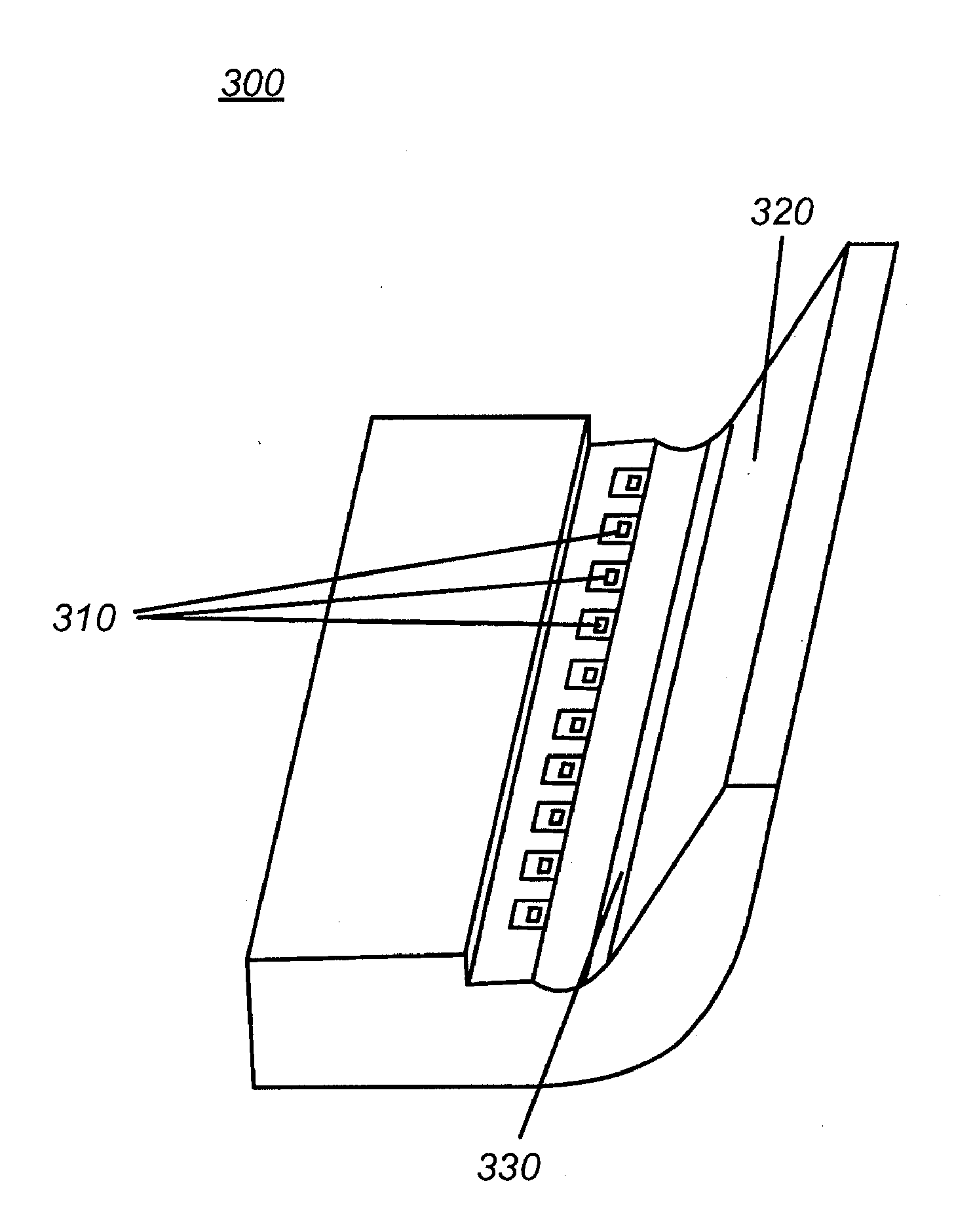
[0258]A lighting unit having one or more of the features described, such as a heat transfer chimney, was tested at multiple Commercially Available LED Production Evaluation and Reporting (CALIPER) approved facilities. The test methods and equipment were National Institute of Standards and Technology (NIST) traceable. The lighting unit had a heat dissipating support structure formed of aluminum, LEDs (e.g., NSSW208A surface mounted LEDs from Nichia Corp. of Tokushima, Japan) mounted on a PCB circuit board, a first optical element, and two second optical elements (e.g., which may have a reflective surface material such as WO-F33 high diffuse reflectance film from WhiteOptics LLC of Newark Del.). In one of the tests, a lighting unit had a luminescent material disposed on a second optical element (e.g., Internatix 05446 Eu doped silicate phosphor from Internatix Corp. of Fremont, Calif.). In another test, the lighting unit did not have the luminescent material.
[0259]Some measurements we...
PUM
 Abstract
Description
Claims
Application Information