Metallic connector, assembly and method of assembly

Inactive Publication Date: 2010-06-03
AFL
View PDF16 Cites 17 Cited by
  • Summary
  • Abstract
  • Description
  • Claims
  • Application Information

AI Technical Summary

Benefits of technology

[0013]It is an object of a preferred embodiment of the present invention to provide a metallic connector which may be connected with the end of a metallic item—preferably a pipe—in a manner which is relatively simple, rapid, and watertight, in order to avoid problems found with traditional connectors.
[0014]It is another object of a preferred embodiment of the present invention to provide a connection in which a metallic part—preferably a pipe or tubular member—is connected with a metallic connector to provide a

Problems solved by technology

This method of connecting pipes is very common, but is not particularly easy or economical.
Such threading machines are usually quite large and difficult to move.
Furthermore, once the ends of the pipe have been threaded, the threads are typically wound with Teflon or with hemp or with some other sealing material to make the joint with the connector watertight, and this procedure takes additional time during assembly of a piping system.
The consequence is that the conventiona

Method used


Image

  • Metallic connector, assembly and method of assembly
  • Metallic connector, assembly and method of assembly
  • Metallic connector, assembly and method of assembly

Examples


Example

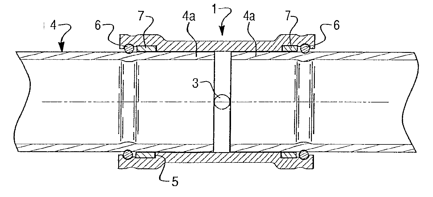
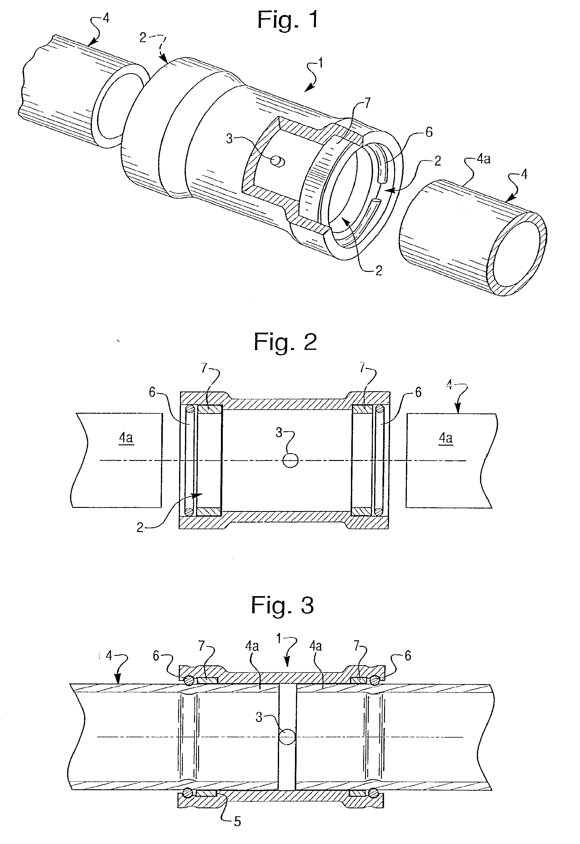
[0024]With reference to FIG. 1, a metallic connector 1 in accordance with a preferred embodiment of the invention is provided in order to connect a first end 4a of a metal pipe 4 with a first end of another metal pipe 4. Although the metallic connector may be used to connect items other than metal pipes, in the preferred embodiments, the metallic connector is used to connect to one or more pipe ends. The ends 4a of the metal pipes 4 are each to be connected to the metallic connector 1 by pressing ends of the metallic connector 1 after the ends 4a of the metal pipes 4 have been inserted into the metallic connector 1 so that the metallic connector and the ends 4a of the metal pipes 4 are pressed together.

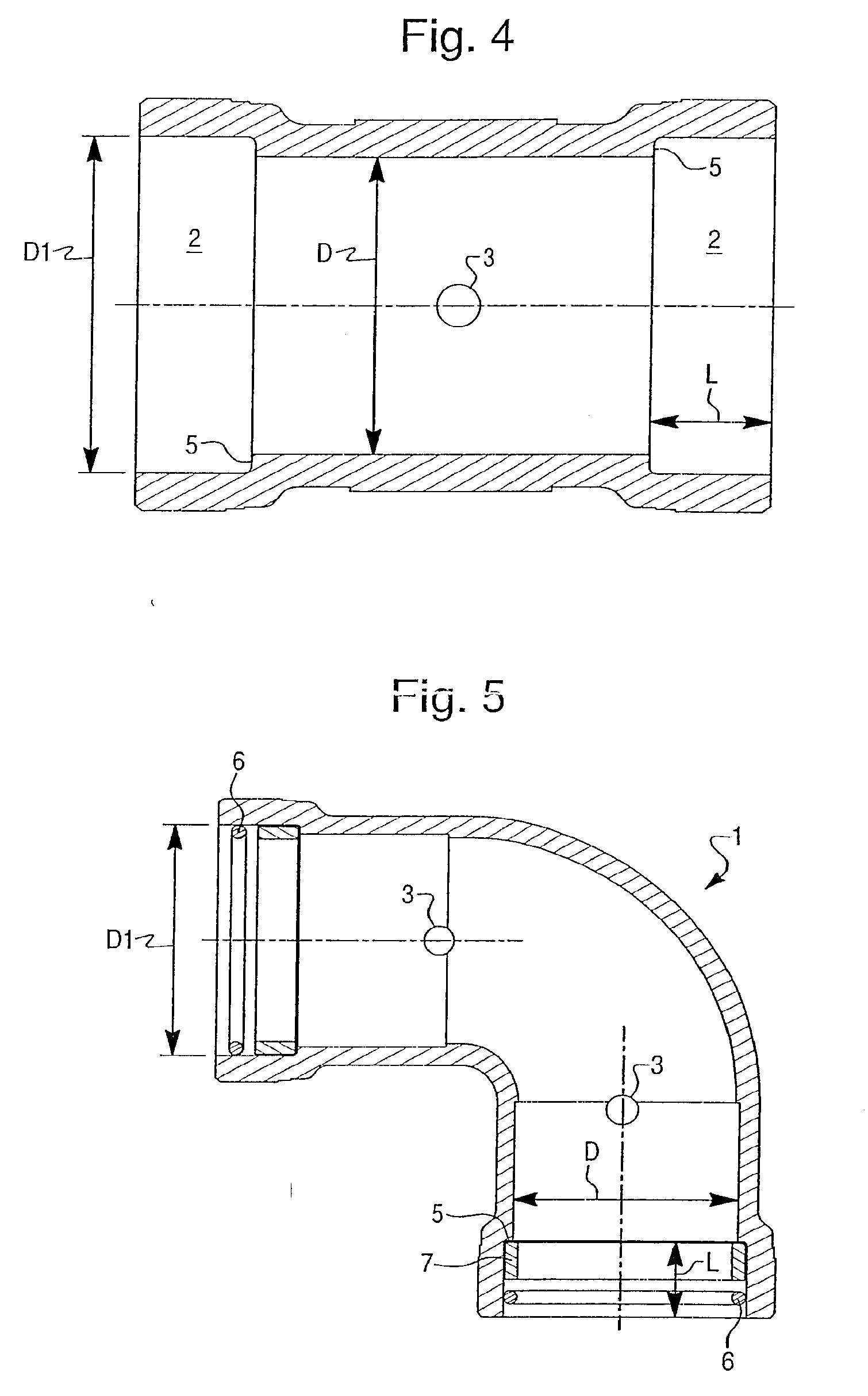
[0025]The metal connector 1 comprises a body with at least one female housing 2. The female housing is formed by an inner wall which is configured to receive the end section 4a of the metal pipe 4 to be connected.

[0026]In the preferred embodiments as shown in the Figs., the metal pipe...


PUM

PropertyMeasurementUnit
Diameteraaaaaaaaaa
Tensile propertiesaaaaaaaaaa
Metallic bondaaaaaaaaaa

Abstract

A metallic connector (1) comprises a female housing (2) in which a retaining ring (6) is made of a material which is harder than the female housing (2) so that the retaining ring (6) is urged into the inner wall of the female housing during a pressing operation. An annular sealing member (7) provides a water tight seal. In the connection assembly, the retaining ring (6) deforms an end of a metallic item (4) provided within the female housing to connect the female housing to the metallic item. The connection assembly is formed by a pressing operation which causes—the retaining ring (6) to deform both the female housing (2) and the metallic item (4) to be connected.

Description

FIELD OF THE INVENTION[0001]The present invention relates generally to metallic connectors which are intended to be used to join metallic parts together by deformation.[0002]In one embodiment, the invention comprises a metallic connector for connection to a metallic pipe or to provide a connection between two or more metallic pipes.[0003]In another embodiment, the invention comprises an assembly comprising a metallic element, which is preferably tubular, that is joined to a metallic connector, and a method of assembly.BACKGROUND OF THE INVENTION[0004]In the building trade, it is well known that piping is used to distribute various fluids such as water and gas. Such piping typically comprises sections of rigid metal pipes, that are usually made of steel, which are threaded together using connectors, that are usually made of cast iron.[0005]The pipes and the connectors are usually screwed together. Typically, the connector (such as an elbow, a coupling, or a T-fitting) has threads whi...

Claims


Application Information

Patent Timeline
IPC IPC(8): F16L33/18F16L13/14
CPCY10T29/49913F16L13/142
Inventor CASTIGLIONI, CLAUDIO MARIAMORALLI, CARLO
Owner AFL
Why Eureka
Try Eureka