Cutting machine with blade depth adjustment

Active Publication Date: 2022-09-22
KRUG & PRIESTER
View PDF11 Cites 0 Cited by
  • Summary
  • Abstract
  • Description
  • Claims
  • Application Information

AI Technical Summary

Benefits of technology

[0008]Accordingly, it is the object of the present invention to develop the blade depth adjustment in a cutting machine of the type mentioned in the intr

Problems solved by technology

Solutions available today to the operator are often difficult to handle since the adjusting elements of the blade depth adjustment are not located on the front face, the main working region of the cutting machine, but for example at the side.
This is a drawback, in particular, when the accessibility is limited at this point due to the point of i

Method used


Image

  • Cutting machine with blade depth adjustment
  • Cutting machine with blade depth adjustment

Examples


Example

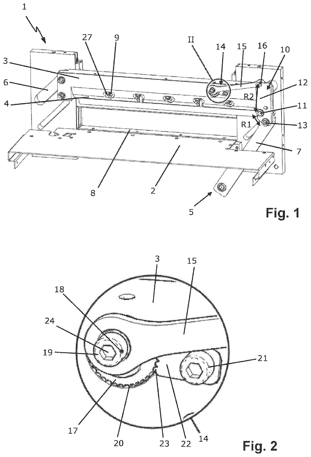
[0021]The cutting machine 1 shown in FIG. 1 comprises a cutting support 2 for the material to be cut, a vertically movable blade bar 3 which bears a blade 4 for cutting the cut material located thereon, and a cutting drive 5 for vertically moving the blade bar 3. The blade bar 3 is mounted in a vertically movable manner in a guide slot 6 running obliquely in this case. The cutting drive 5 is manually actuated or electrically driven and is motion-coupled to the blade bar 3 via a vertically movable drive connecting rod 7, the lower reversal point thereof defining the lower reversal point of the blade movement.

[0022]A cutting strip 8 which is generally inserted flush in the cutting support 2 serves as a counterpart for the blade cutter. Since the blade 4 is also designed to separate the lowermost layer of a cut material stack, the blade 4 has to penetrate minimally into the cutting strip 8. The cutting strip 8 is generally produced from plastics; this provides, on the one hand, suffici...


PUM


Abstract

A cutting machine has a cutting support for material to be cut, with a vertically movable blade bar which bears a blade for cutting the cut material located thereon. A cutting drive is for vertically moving the blade bar. A blade depth adjustment is for vertically adjusting the blade bar relative to a vertically movable drive element of the cutting drive. The blade depth adjustment includes a deflection lever which is pivotably mounted about a horizontal axis on the blade bar. The drive element can be articulated thereon at a first radial distance to the horizontal axis. An adjusting mechanism may act on the deflection lever at a second radial distance to the horizontal axis, for rotating and fixing the deflection lever.

Description

CROSS-REFERENCE TO RELATED APPLICATIONS[0001]This application claims priority to European Application No. 21 163 033.0 filed Mar. 17, 2021, the entire contents of which are hereby incorporated in full by this reference.DESCRIPTIONField of the Invention[0002]The invention relates to a cutting machine with a cutting support for material to be cut, with a vertically movable blade bar which bears a blade for cutting the cut material located thereon, with a cutting drive for vertically moving the blade bar and with a blade depth adjustment for vertically adjusting the blade bar relative to a vertically movable drive element of the cutting drive.Background of the Invention[0003]Cutting machines generally have a mechanical structure which moves a blade manually by the action of force by the operator or electrically driven from top to bottom through a material to be cut, such as for example a paper stack. A cutting counter support in the form of a cutting strip is required as a counterpart ...

Claims


Application Information

Patent Timeline
IPC IPC(8): B26D5/02
CPCB26D5/02B26D1/08B26D5/18B26D7/2628B23D35/005
Inventor JENTER, HOLGER
Owner KRUG & PRIESTER
Why Eureka
Try Eureka