Feed carrier receptacle for use in rotary feed dispensing mechanism

Inactive Publication Date: 2013-02-28
CIXI HAOSHENG ELECTRONICS & HARDWARE
View PDF3 Cites 10 Cited by
  • Summary
  • Abstract
  • Description
  • Claims
  • Application Information

AI Technical Summary

Benefits of technology

[0013]A further objective of the present invention is to arrange the coupling section at a center of the bottom of the box and extending into the box and to have each of the separation partitions extending outward from the coupling section t

Problems solved by technology

However, in case of insufficiency in number or size of the feed crib, animals may push each other for feeding, leading to fall and injury of animals and eventually causing an economic loss of animal owner or feeder.
Further, since the site of feeding is crowded and concentrated, occupation of the site by some of the animals having large sizes for solely feeding may be found, making it not possible for anima

Method used


Image

  • Feed carrier receptacle for use in rotary feed dispensing mechanism
  • Feed carrier receptacle for use in rotary feed dispensing mechanism
  • Feed carrier receptacle for use in rotary feed dispensing mechanism

Examples


Example

[0026]The following descriptions are exemplary embodiments only, and are not intended to limit the scope, applicability or configuration of the invention in any way. Rather, the following description provides a convenient illustration for implementing exemplary embodiments of the invention. Various changes to the described embodiments may be made in the function and arrangement of the elements described without departing from the scope of the invention as set forth in the appended claims.

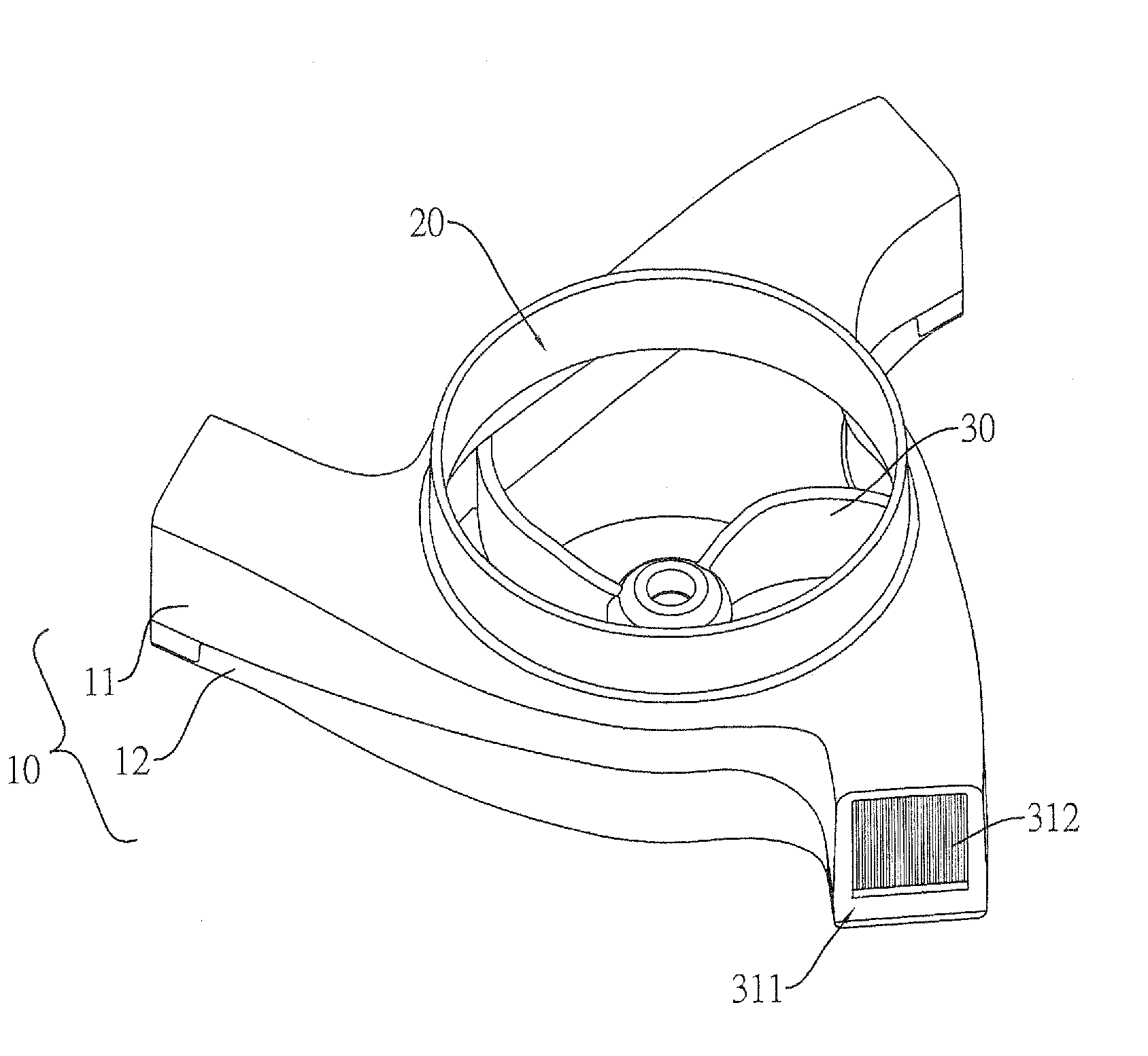
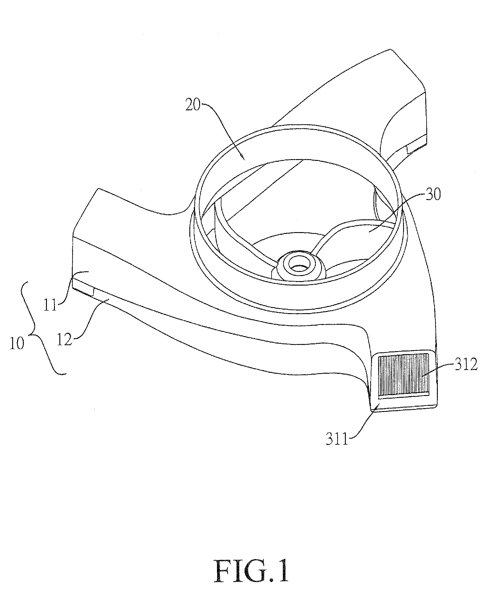
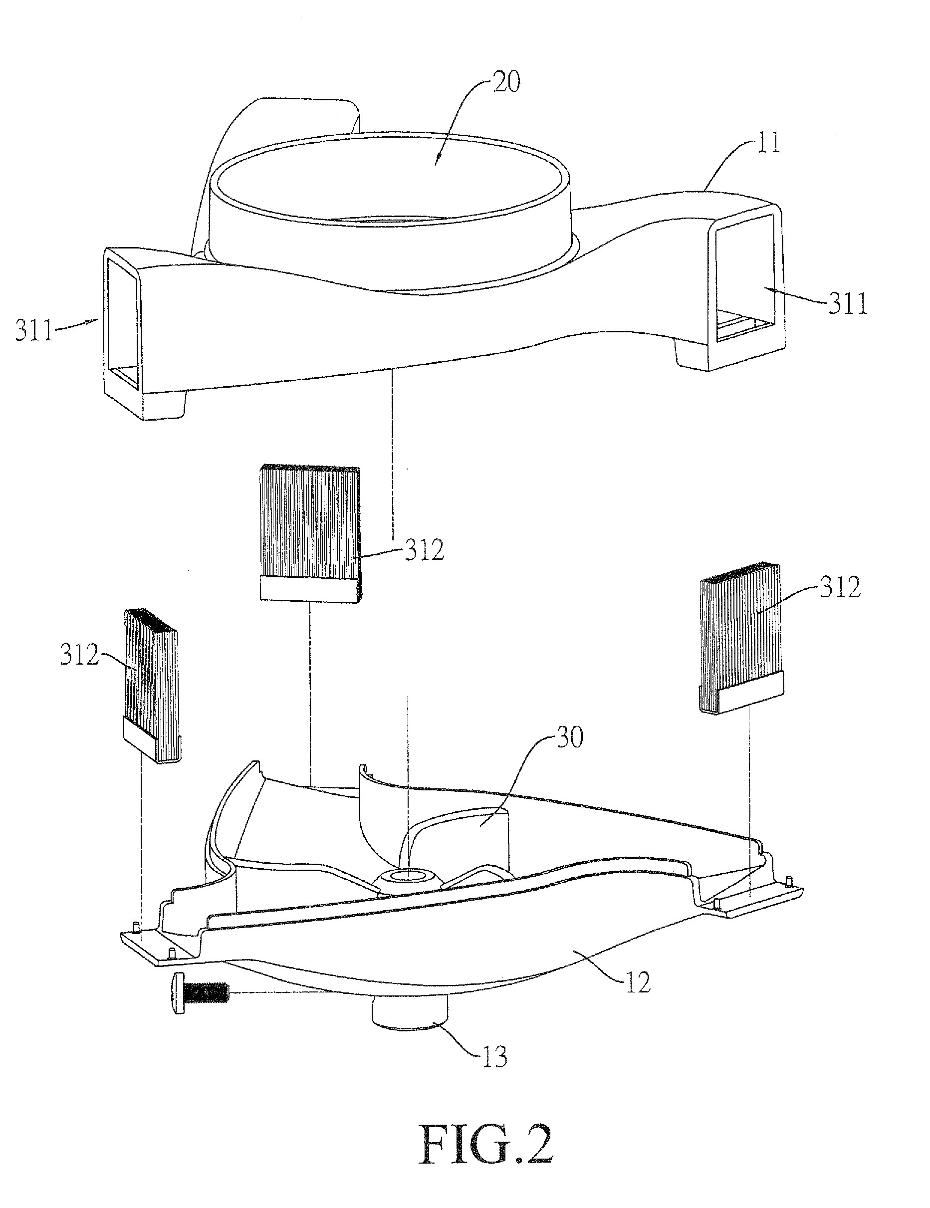
[0027]Reference is now made to FIG. 1, which is a perspective view of an embodiment of the present invention, FIG. 2, which is an exploded view of the embodiment of the present invention, FIG. 3, which is a perspective view of a carrier body of the embodiment of the present invention, and FIG. 4, which is a top plan view of the carrier body of the embodiment of the present invention.

[0028]The embodiment of the present invention is applicable to a feed carrier receptacle of rotary feed dispensing mec...


PUM


Abstract

Disclosed is a feed carrier receptacle for use in a rotary feed dispensing mechanism, which includes a box, a feed loading opening, and separation partitions. The feed loading opening is formed in the box. The separation partitions are arranged inside the box and every adjacent separation partitions and an inside surface of the box form a feed compartment, which communicates the feed loading opening and is provided with a feed discharge opening and a brush adjacent to the feed discharge opening. When put into rotation, the feed loaded in the receptacle is generally rotated in unison therewith to move toward the feed discharge openings and is subject to a frictional force as contacting the brush so that the feed, when passing through the brush, is caused to rotate by itself and thus may fly over a long distance. This increases the distribution range of feed.

Description

(a) TECHNICAL FIELD OF THE INVENTION[0001]The present invention generally relates to a receptacle for receiving and containing feed, and more particularly to a feed carrier receptacle that is combinable with a feed dispensing mechanism to dispense and distribute feed.(b) DESCRIPTION OF THE PRIOR ART[0002]To breed and raise animals, such as poultry, in a wide range, it is important to handle feed dispensing and distribution in order to benefit the growth of the animals.[0003]Conventionally, feed is supplied through an elongate feed crib, which allows animals to feed themselves. However, in case of insufficiency in number or size of the feed crib, animals may push each other for feeding, leading to fall and injury of animals and eventually causing an economic loss of animal owner or feeder. Further, since the site of feeding is crowded and concentrated, occupation of the site by some of the animals having large sizes for solely feeding may be found, making it not possible for animals ...

Claims


Application Information

Patent Timeline
IPC IPC(8): A01K5/00
CPCA01K39/014A01K5/0225
Inventor CHANG, SHIH-MINGCAO, JIN-JUN
Owner CIXI HAOSHENG ELECTRONICS & HARDWARE
Why Eureka
Try Eureka