Thermal management system for a multi-cell array

a technology of thermal management system and multi-cell array, which is applied in the field of batteries, can solve the problems of increasing the cost and weight of the battery, and the excessive amount of material used in the thermal management of multi-cell batteries, so as to remove thermal energy, remove thermal energy, and remove thermal energy.

Inactive Publication Date: 2013-02-28
GENERAL ELECTRIC CO
View PDF8 Cites 21 Cited by
  • Summary
  • Abstract
  • Description
  • Claims
  • Application Information

AI Technical Summary

Benefits of technology

[0009]In an embodiment, a thermal management system for an electrochemical device is provided having means for directing an air flow along a first outer side region adjacent to a plurality of electrochemical cells to remove thermal energy generated, at least in part, by the plurality of electrochemical cells. The thermal management system also has means for redirecting at least a portion of the air flow from along the first outer side region to along a second outer side region adjacent to the plurality of electrochemical cells that is perpendicular to the first outer side region to further remove thermal energy generated, at least in part, by the plurality of electrochemical cells. The thermal management system further has means for redirecting at least a portion of the air flow from along the second outer side region to along a third outer side region adjacent to the plurality of electrochemical cells that is perpendicular to the second outer side region to further remove thermal energy generated, at least in part, by the plurality of electrochemical cells.

Problems solved by technology

Current methods of thermally managing multi-celled batteries often employ an excessive amount of material within the battery, for example in the form of cooling panels between rows of electrochemical cells which have to be tied together using manifolds.
Such methods can add significant cost and weight to the battery.

Method used


Image

  • Thermal management system for a multi-cell array
  • Thermal management system for a multi-cell array
  • Thermal management system for a multi-cell array

Examples


Embodiment Construction

[0021]Embodiments relate to a thermal management system for an energy storage system. With reference to the drawings, like reference numerals designate identical or corresponding parts throughout the several views. However, the inclusion of like elements in different views does not mean a given embodiment necessarily includes such elements or that all embodiments of the invention include such elements.

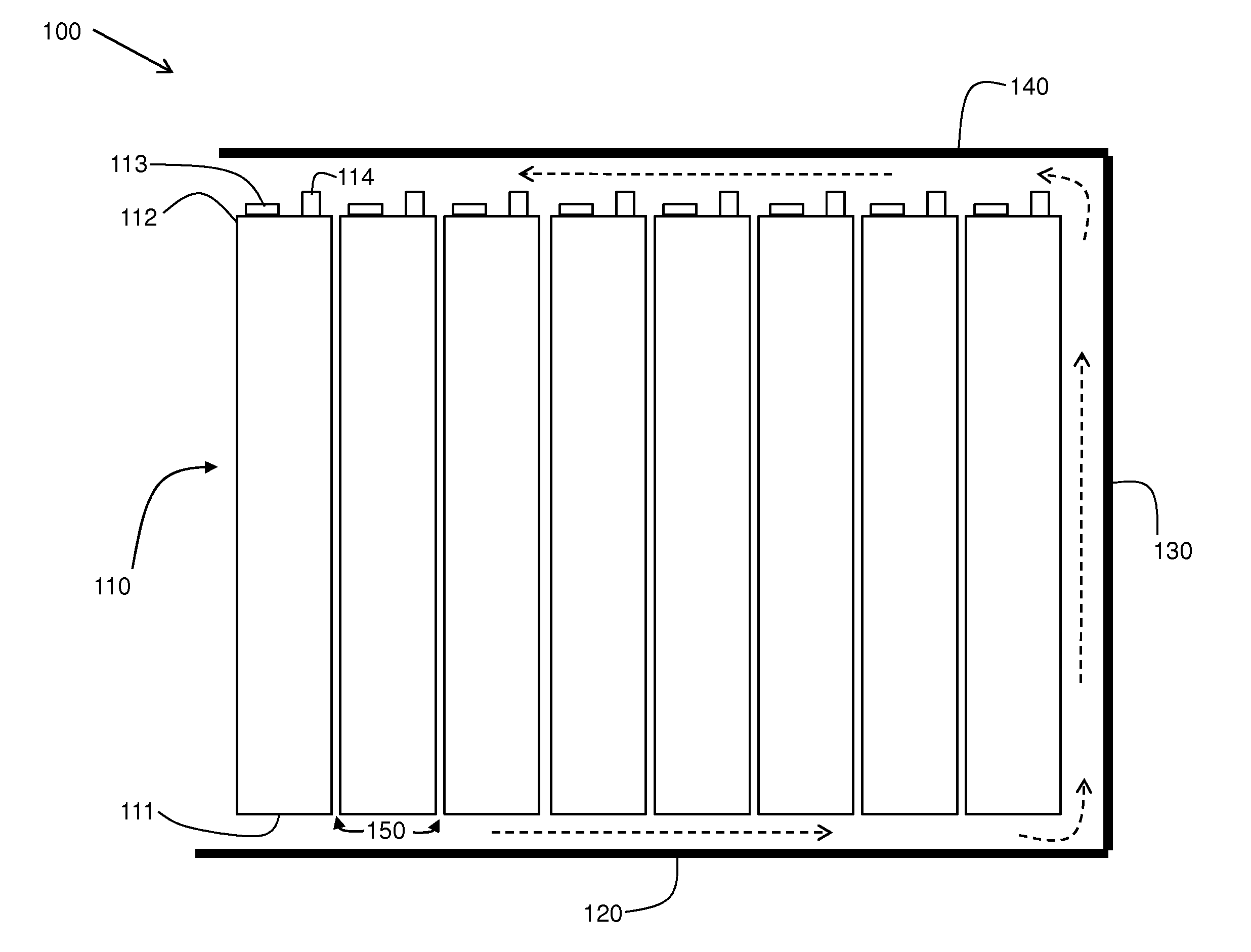
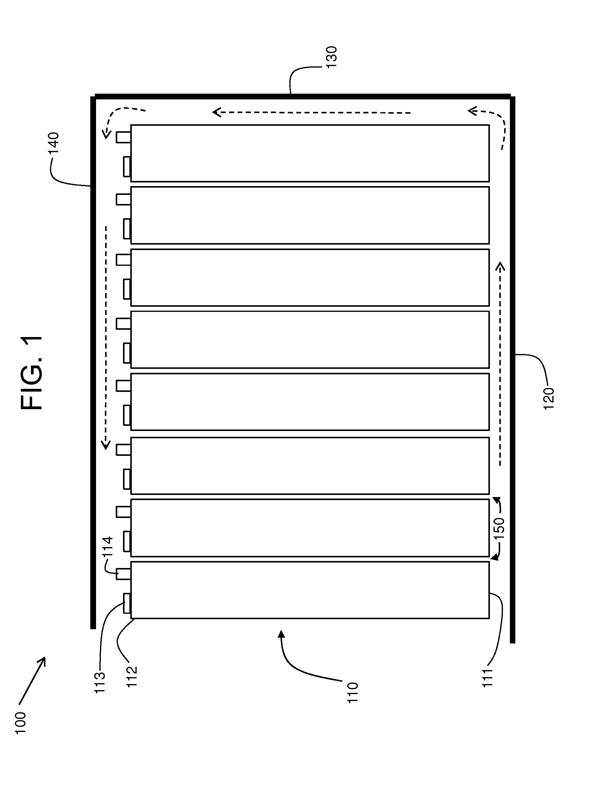
[0022]FIG. 1 illustrates the broad concept of an energy storage system 100 having a thermal management system, in accordance with various embodiments. The thermal management system has several elements as is discussed herein. The energy storage system 100 includes a plurality of electrochemical cells 110 for storing energy. The electrochemical cells 110 are arranged adjacent to each other to form an array of electrochemical cells 110. For example, in accordance with an embodiment, sixty-four electrochemical cells 110 can be arranged as an array of eight cells by eight cells in, for exa...


PUM

PropertyMeasurementUnit
heightaaaaaaaaaa
widthaaaaaaaaaa
operating temperatureaaaaaaaaaa

Abstract

A thermal management system for an energy storage system that controls the temperature of an array of electrochemical cells of the energy storage system. Fluid channels or pathways are provided around outer side regions of an array of electrochemical cells. Fluid flow is directed along one pathway to a next subsequent pathway, absorbing thermal energy generated by the array of electrochemical cells along the way. The fluid flow is eventually discharged from the energy storage system by the thermal management system, thereby removing thermal energy from the energy storage system.

Description

BACKGROUND[0001]1. Technical Field[0002]The subject matter disclosed herein relates to batteries and, more particularly, to a thermal management system for a battery having an array of electrochemical cells.[0003]2. Discussion of Art[0004]Multi-celled batteries for storing energy are sensitive to temperature and may operate more effectively at a particular temperature or within a particular temperature range. Current methods of thermally managing multi-celled batteries often employ an excessive amount of material within the battery, for example in the form of cooling panels between rows of electrochemical cells which have to be tied together using manifolds. Such methods can add significant cost and weight to the battery.[0005]It would therefore be desirable to develop a battery with thermal management features and characteristics that differ from those of batteries that are currently available.BRIEF DESCRIPTION[0006]In an embodiment, a thermal management system is provided having a...

Claims


Application Information

Patent Timeline
Patent Type & Authority Applications(United States)
IPC IPC(8): H01M10/50H01M2/02
CPCH01M10/5004H01M10/5008H01M10/5071H01M10/5057H01M10/5032H01M10/613H01M10/617H01M10/647H01M10/6556H01M10/6565Y02E60/10
Inventor BULL, ROGER NEILSUDWORTH, PAULTOWLE, STUART MARTIN
Owner GENERAL ELECTRIC CO
Why Eureka
Try Eureka